Popular Courses
PHYSICS 1202A/B
Western University
PHYSICS 1E03
McMaster University
PHYSICS 1402A/B
Western University
PHYS 205
Concordia University
PHYS 142
McGill University
ENGG 212
University of Calgary
PHY132H1
University of Toronto
PHY132H1
University of Toronto
PHYS 102B
University of Victoria
PHYS-1300
University of Windsor
PHY 1121
University of Ottawa
PHYS 121
University of Waterloo
PHYSICS 1102A/B
Western University
PHYS 227
University of Calgary
SC/PHYS 2020 3.00
York University
PHYS 116
Queen's University
PHY 9B
University of California - Davis
PHY 131
Arizona State University - Tempe
MCG 1101
University of Ottawa
PHYS 1010
York University
0:00 / 0:00
Mutual Inductance
In this section, we describe how systems can induce changes in each other by electromagnetic induction.
- Consider two sets of coils that are beside each other (we'll call them set 1 and set 2).
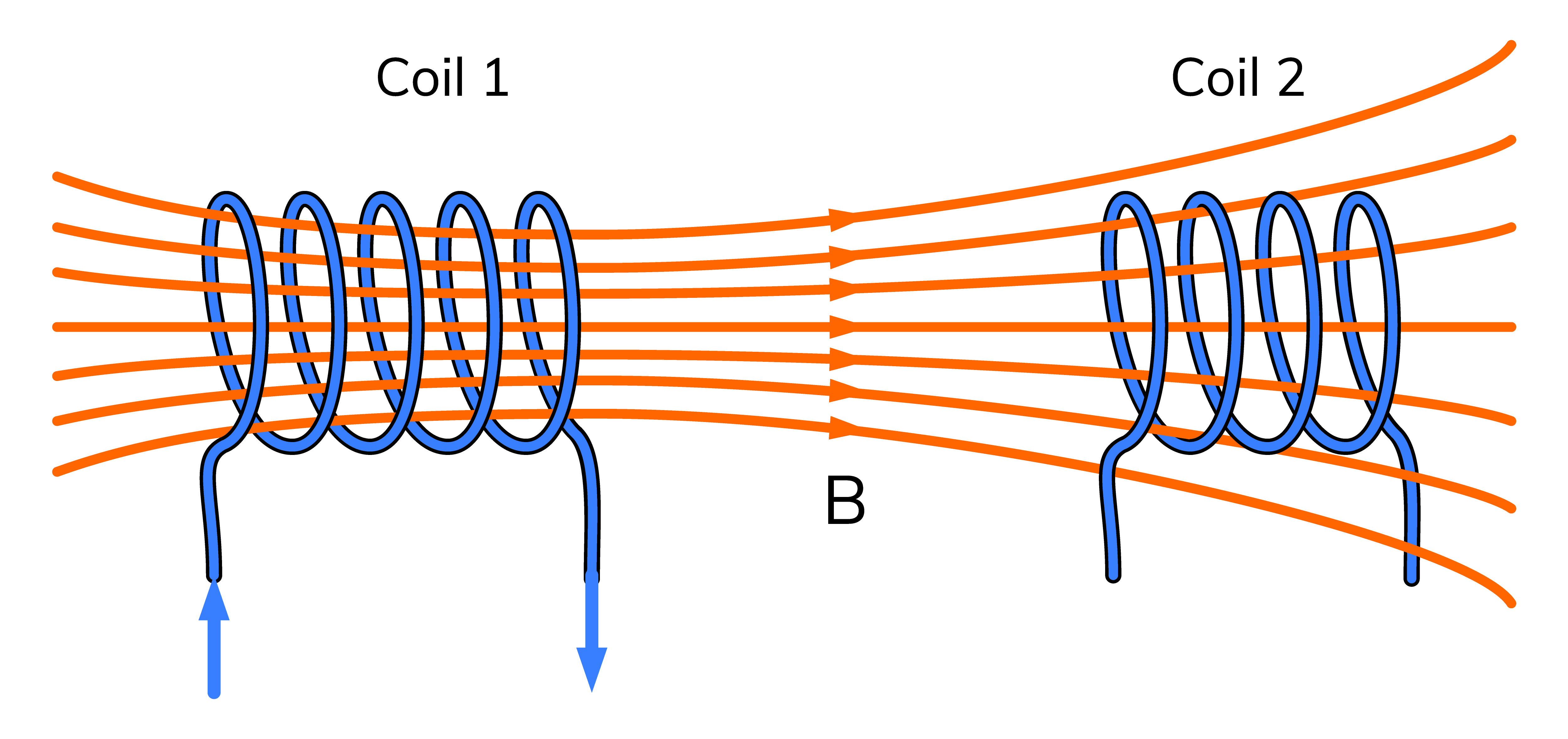
- If the current in set 1 of coils changes, this will induce a magnetic field from set 1.
- This new magnetic field is detected in set 2.
- An induced current appears in set 2, reacting to the change in magnetic flux.
- Because the two sets of coils affect each other, we say that the system has a mutual inductance (M):
- Mutual inductance is measured in SI units of Henry (H).
Wize Tip
The negative sign in these formulas is a statement of Lenz's Law.
Wize Concept
A high mutual inductance means the two sets of coils react strongly in response to changes in the other set, or that the system is strongly coupled.
Likewise, a low mutual inductance means the sets do not react as strongly, or the system is weakly coupled.
0:00 / 0:00
Example: Mutual Inductance
Consider two sets of coils that are near each other. In one set of coils, a change in current from zero to 6.0 A in two seconds results in a detected voltage of 0.5 V in the other set of coils.
a) What is the mutual inductance of this system?
b) Qualitatively, what do you think would happen to the mutual inductance if the two systems were brought much closer together?
Part a)
We simply plug the values into the mutual equation formula:
Part b)
The magnetic field that reaches the second set of coils from the first set of coils would realistically be stronger now that the systems are much closer together. As a result, we might also expect a stronger reaction than 0.5 V from the second set of coils as a result of this current change.
In other words, the mutual inductance of the system has increased.
0:00 / 0:00
Self-Inductance and Inductors
It turns out that having materials that can resist changes to magnetic flux have widespread applications in science and engineering.
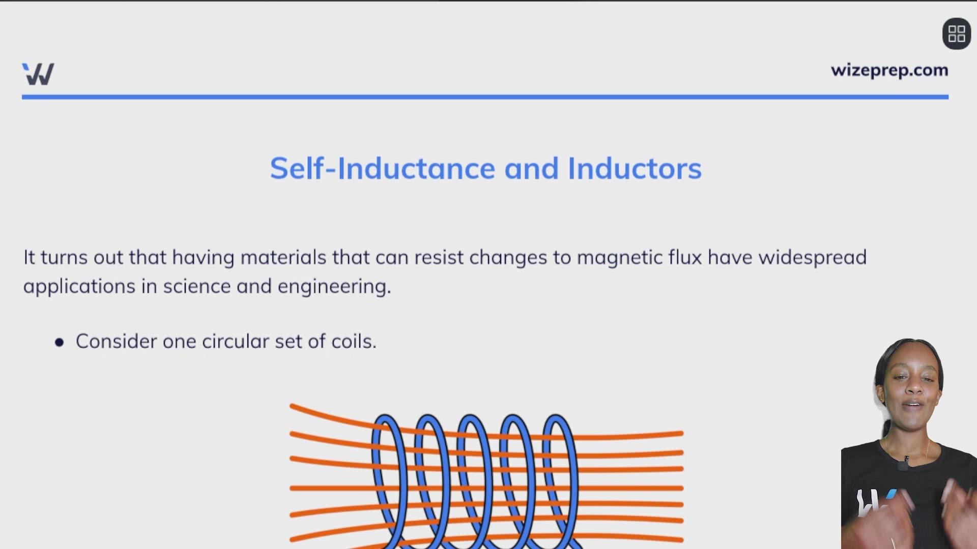
- Consider one circular set of coils.

- If the current through the coils changes, an induced magnetic field will appear.
- By Lenz's Law, the coils themselves will produce a new magnetic field in the opposite direction.
- This results in resisting the change in current, and producing a back emf.
- The relationship between the change in current and emf produced depends on the self-inductance (L) of the system:
- Self-inductance (L) is measured in SI units of Henry (H).
- Devices that are designed to resist changes in circuits are called inductors.
Wize Tip
In most cases, self-inductance is simply called inductance.
Wize Concept
Systems with high self-inductance produce very strong back emfs and have a stronger resistance to changes in current.
Inductance of a device
- The inductance of a device depends only on geometric and material properties (e.g. shape, size, composition).
- Let's apply Faraday's Law to the inductor equation:
- This can also be written as .
Wize Tip
This result tells us that a high inductance (L) means that even for a small change in current, there is a large magnetic flux produced to counter the change - exactly as we would expect.
Practice: Self-Inductance
Consider a system that is safely designed to carry high currents. It carries 300 A of current and has an inductance of 0.30 H.
a) If we were to abruptly shut off this current (over a time of one millisecond), what would be the induced emf through the system?
b) What is the fastest we could shut off the current to prevent the induced emf from exceeding 100 V?
0:00 / 0:00
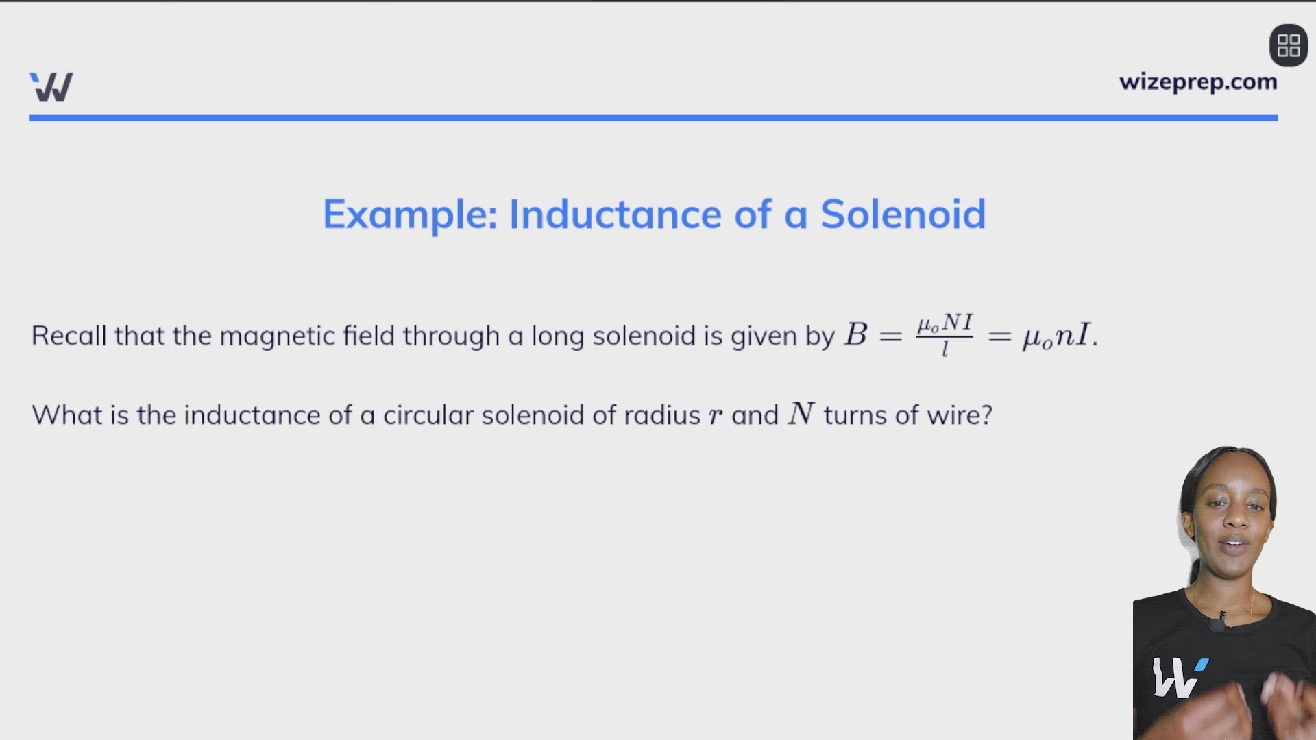
Example: Inductance of a Solenoid
Recall that the magnetic field through a long solenoid is given by .
What is the inductance of a circular solenoid of radius and turns of wire?
It turns out that solenoids are one of very few circuit arrangements where we can actually find an equation for inductance. This is because solenoids have a constant and uniform magnetic field that is easy to work with.
We start with the relationship between magnetic flux, current, and inductance.
Consider a change in magnetic flux through the solenoid. The flux for a solenoid is given as follows:
The change in this flux would be caused by a change in the current in the solenoid (all of the other variables are geometric only):
Plugging this back into the relationship above, we see that the change in current cancels out, and we find an expression for the inductance of a solenoid which depends only on geometric variables (as it should!)