
Power Dissipation in RLC Circuits
In circuit design scenarios, the power for the source and circuit elements is an important consideration.
- For AC circuits, the instantaneous power changes constantly. We usually use average power instead.
- The average power dissipated by a resistor is as follows:
- The average power generated by the source is as follows:
- In this equation, is the phase angle, and the term is called the power factor.
- At resonance, , so the average power generated by the source is a maximum.
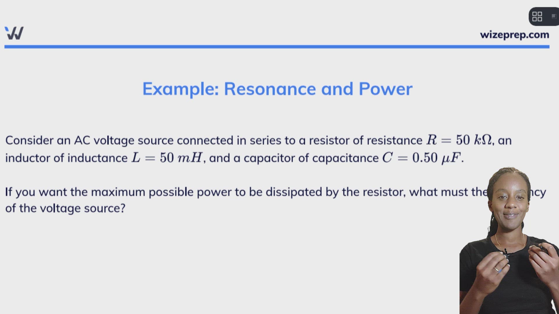
Example: Resonance and Power
Consider an AC voltage source connected in series to a resistor of resistance , an inductor of inductance , and a capacitor of capacitance .
If you want the maximum possible power to be dissipated by the resistor, what must the frequency of the voltage source?
The maximum amount of power is dissipated in the resistor when the RLC circuit is at resonance. This is when the current is the strongest, so the power dissipated in the resistor is the highest.) At resonance, , so the power factor is .
Let's find the frequency (not the angular frequency!) that corresponds to the resonance condition for this circuit.
Note - our answer does not depend on resistance!