Wize University Physics Textbook (Master) > AC Circuits
AC Circuits in Parallel
Popular Courses
PHYSICS 1E03
McMaster University
PHYSICS 1402A/B
Western University
PHYS 205
Concordia University
PHYS 142
McGill University
ENGG 212
University of Calgary
PHY132H1
University of Toronto
PHY132H1
University of Toronto
PHYS-1300
University of Windsor
PHY 1121
University of Ottawa
PHYS 121
University of Waterloo
PHYSICS 1102A/B
Western University
PHYS 227
University of Calgary
SC/PHYS 2020 3.00
York University
PHY 9B
University of California - Davis
PHY 131
Arizona State University - Tempe
MCG 1101
University of Ottawa
PHYS 1010
York University
PHYS 1020
University of Manitoba
PHYS 1007
Carleton University
PHY 9A
University of California - Davis

0:00 / 0:00
Parallel RLC Circuits (AC)
In this section, we will use Kirchhoff's rules to analyze AC circuits connected in parallel.
- Consider an alternating voltage source of frequency and maximum voltage connected in parallel to a resistance , an inductance , and a capacitance .

- Following Kirchhoff's loop rule, the voltage supplied to each branch is equal:
- Following Kirchhoff’s junction rule, the sum of currents through each element must equal the total current from the source.
- Since the currents are out of phase, they must be added together as vectors, using phasor diagrams.
Wize Tip
For series RLC circuits, the current from the source is the "reference" phasor.
For parallel RLC circuits, the voltage from the source is used as the "reference" phasor instead.
Wize Concept
For each branch of the parallel circuit, the relative angle between current and voltage is identical to a series circuit.
- The impedance of a parallel RLC circuit is given as follows:
- The maximum total current from the source is related to the maximum source voltage by Ohm's Law:
Wize Tip
At resonance (), the impedance once again equals the resistance from the resistor.
Watch Out!
For parallel RLC circuits, the current drawn from the source is a minimum at resonance. This is the opposite of series RLC circuits where the current drawn at resonance is a maximum.
- The phase angle for parallel RLC circuits can be written in a few different ways:
Wize Concept
At resonance for parallel RLC circuits, the current and voltage are in phase (same as series RLC circuits).
0:00 / 0:00
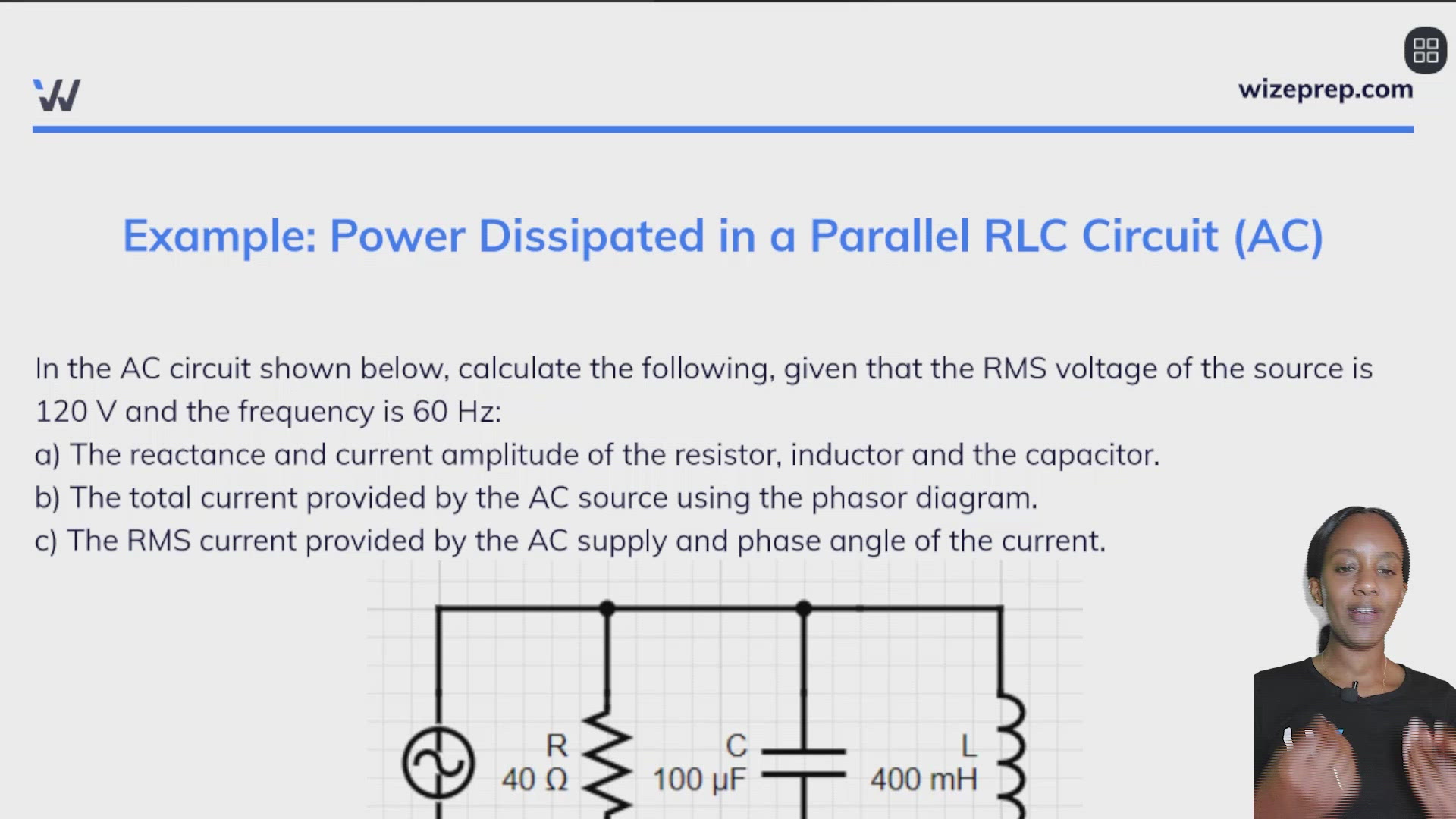
Example: Power Dissipated in a Parallel RLC Circuit (AC)
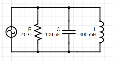
In the AC circuit shown below, calculate the following, given that the RMS voltage of the source is 120 V and the frequency is 60 Hz:
a) The reactance and current amplitude of the resistor, inductor and the capacitor.
b) The total current provided by the AC source using the phasor diagram.
c) The RMS current provided by the AC supply and phase angle of the current.
First, let's quickly find the angular frequency and the maximum voltage, as we will need them:
Part a)
To find the reactances, we can just plug values into the formulas as usual:
The capacitor:
The inductor:
For the resistor, the reactance is equal to the resistance (40 Ohms).
To find the current amplitudes, we can use Ohm's Law in each branch.
Part b)
For RLC AC circuits in parallel, we need to add currents like vectors - we can an analogous equation to the impedance.
(Tip: think of as the horizontal component of the vector, and is the vertical component of the vector; then we are finding the magnitude of a vector ).
Part c)
Finding the RMS current from the source is straightforward, since we already have the maximum current drawn from the source:
To find the phase angle, we can use the phase angle formula:
Note, you can prove to yourself that the above formula is equivalent to the one below:
Since the question asked for the phase angle of the current, our final answer is +0.89 radians.
Practice: Power Dissipated in a Parallel RLC Circuit (AC)
Consider an alternating current voltage source (frequency 400 Hz, voltage amplitude 100 V) connected in parallel to the following circuit elements: a resistor of resistance , a capacitor with capacitance , and an inductor with inductance .
a) What is the current amplitude drawn from the voltage source?
b) What is the phase angle of the current relative to the voltage?
c) Find the maximum current through the resistor, the capacitor, and the inductor.
Part a)