Wize University Physics Textbook (Master) > AC Circuits
High-Pass and Low-Pass Filters
Popular Courses
PHYSICS 1E03
McMaster University
PHYSICS 1402A/B
Western University
PHYS 205
Concordia University
PHYS 142
McGill University
ENGG 212
University of Calgary
PHY132H1
University of Toronto
PHY132H1
University of Toronto
PHYS-1300
University of Windsor
PHY 1121
University of Ottawa
PHYS 121
University of Waterloo
PHYSICS 1102A/B
Western University
PHYS 227
University of Calgary
SC/PHYS 2020 3.00
York University
PHY 9B
University of California - Davis
PHY 131
Arizona State University - Tempe
MCG 1101
University of Ottawa
PHYS 1010
York University
PHYS 1020
University of Manitoba
PHYS 1007
Carleton University
PHY 9A
University of California - Davis

0:00 / 0:00
High-Pass and Low-Pass Filters
Real-world signals often contain signals of mixed frequency, or have frequencies that change. Since the behaviour of an AC circuit depends on frequency, filters are introduced so that circuits are robust to unexpected or varying inputs.
Fundamentals
- In circuits where there are branches, more current travels through paths where there is less resistance, and less current travels through paths where there is more resistance.
- In AC circuits with capacitors and inductors, reactance plays the role of resistance.
Write it Down
At low frequencies, inductors have low reactance, and capacitors have high reactance.
At high frequencies, inductors have high reactance, and capacitors have low reactance.
High-Pass Filters
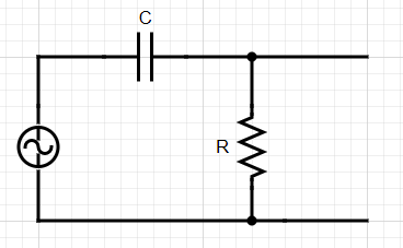
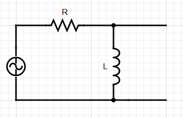
- As the name suggests, high-pass filters allow only high frequency signals to continue through a circuit.
- We can construct a high-pass filter with a capacitor or an inductor:
Low-Pass Filters
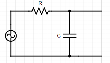
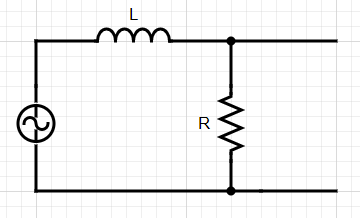
- Low-pass filters allow only low-frequency signals to pass through the circuit.
- Like high-pass filters, we can either use a capacitor or an inductor to construct a low-pass filter, but they are in the opposite positions.
Wize Tip
When a circuit element has a very, very low reactance, you can conceptualize the circuit by replacing that circuit element with a simple wire.

0:00 / 0:00
Example: High-Pass and Low-Pass RC Filters
a) For an RC high-pass or low-pass filter, derive the cutoff frequency. This is the frequency where the resistance of the resistor is equal to the reactance of the capacitor.
b) For an RC low-pass filter (as shown below), show that the output-to-input voltage ratio is given by the following expression:

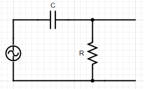
c) Derive the output-to-input voltage ratio for an RC high-pass filter, as shown below:
Part a)
For this part, all we need to do is set the resistance equal to capacitive reactance, and solve for frequency. This will be the cutoff frequency.
Part b)
The output-to-input ratio is given by the ratio of the capacitive reactance to the total filter impedance:
Remember, this is a low-pass filter. That means high-frequency signals should not have an output. If we set the frequency to a very high value (), this ratio becomes 0.
Part c)
We follow a similar procedure to above, except we use the ratio of resistance to impedance instead, since the circuit elements are in a different order.
From here we can simplify in two different ways. We can either factor out an from the denominator,
or we can multiply both the numerator and denominator by :
Either of these expressions are fine, although the second expression is easier to compare with the expression from part (b).
This is a high-pass filter, so low frequency signals should not get through. If we take the small frequency limit (), the ratio goes to zero. (This is easier to see with the first expression above.)