Wize University Physics Textbook (Master) > AC Circuits
RLC Circuits and Resonance
Popular Courses
PHYSICS 1E03
McMaster University
PHYSICS 1402A/B
Western University
PHYS 205
Concordia University
PHYS 142
McGill University
ENGG 212
University of Calgary
PHY132H1
University of Toronto
PHY132H1
University of Toronto
PHYS 102B
University of Victoria
PHYS-1300
University of Windsor
PHY 1121
University of Ottawa
PHYS 121
University of Waterloo
PHYSICS 1102A/B
Western University
PHYS 227
University of Calgary
SC/PHYS 2020 3.00
York University
PHY 9B
University of California - Davis
PHY 131
Arizona State University - Tempe
MCG 1101
University of Ottawa
PHYS 1010
York University
PHYS 1020
University of Manitoba
PHYS 1007
Carleton University

0:00 / 0:00
RLC Circuits (AC)
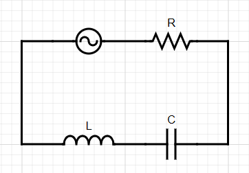
When we have both a capacitor and an inductor in a series AC circuit, the capacitor and inductor have competing effects on the total circuit behaviour.
- Consider an RLC circuit with resistance , capacitance , inductance , and an AC source with frequency and maximum voltage .
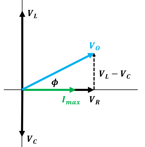
- The most general phasor diagram applies to this system:
Wize Tip
If the downward-pointing phasor for capacitance is larger than the upward-pointing phasor for inductance, the resultant source vector phasor will point below the horizontal axis, instead of above it.
- To find the relationship between current and voltage, we can use the impedance.
- This gives the current:
- The phase angle is given by the usual formula:
Wize Concept
For alternating RLC circuits, the voltage can either lag or lead the current - it depends on the capacitance and inductance values.
Write it Down
For a series AC circuit, the instantaneous current provided by the battery is always equal for all current elements.
0:00 / 0:00
Example: RLC Circuit in Series (AC)
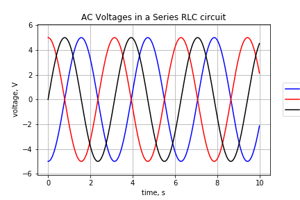
In the diagram below for an LRC circuit, if the black line (#3) is the voltage across the resistor:
a) Which line represents the voltage across the capacitor?
b) Which line represents shows the voltage across the inductor?
c) If we know that the maximum current passing through the circuit is 2 A, what are the values for resistance, inductive reactance, capacitive reactance, and impedance?
d) What is the angular frequency of the oscillations?
e) What are inductance and capacitance values?
Part a)
We know the voltage across the capacitor lags behind the voltage of the resistor, so the maximum voltage for the capacitor must occur AFTER the maximum voltage for the resistor. Therefore, the blue line (line 2) represents the voltage across the capacitor.
Part b)
The max voltage across the inductor happens BEFORE the max voltage across the resistor, so the red line (line 1) must represent the inductor voltage.
Part c)
The maximum voltage across each element can be read off of the graph - they are all 5.0 V. The maximum current is equal for all elements since the circuit is in series, and we are told that it is equal to 2.0 A.
We can find the resistance and reactances with Ohm's Law.
We can now find the impedance. Note that the inductive reactance and capacitive reactance are equal, so we must be at the resonance condition.
Part d)
We need to use more information from the graph to find the angular frequency. The period of oscillation can be read from the graph as approximately 6.3 seconds (it is meant to be , but a reasonable approximation is OK here if you don't read it as exactly 6.3).
Part e)
The inductance and capacitance can be found from the definitions of reactance:
0:00 / 0:00
Resonance
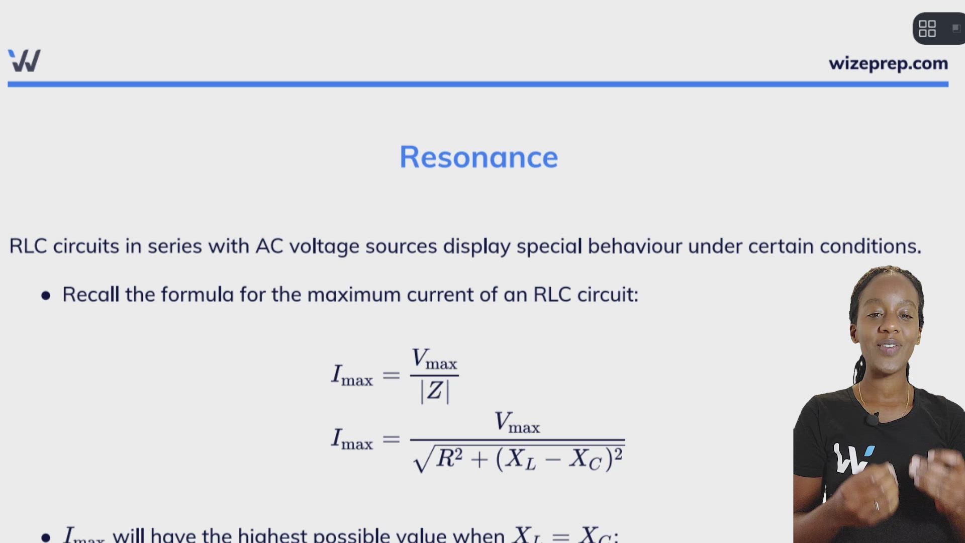
RLC circuits in series with AC voltage sources display special behaviour under certain conditions.
- Recall the formula for the maximum current of an RLC circuit:
- will have the highest possible value when :
- This condition is called the resonance condition.
Wize Tip
At resonance, the total impedance from all circuit elements equals the resistance from the resistor.
- Resonance only occurs for specific circuit parameters:
- Let's consider the phase angle at resonance:
Wize Concept
At the RLC series resonance condition:
- the current and source voltage are in phase;
- the current provided by the source will reach a maximum.
Practice: RLC Circuit (AC) and Resonance
A series RLC circuit contains a capacitor with capacitance and an inductor with inductance . If the peak-to-peak value of the source voltage is equal to 200 V:
a) Find the resonant angular frequency of this circuit.
b) Find the resistance required such that the maximum current passing through capacitor is equal to 2.0 A.
c) Find the maximum voltage across inductor at this resonance condition.
Part a)
Practice: Output-to-Input Ratios for an RLC Series Circuit (AC)
Consider the AC circuit below, where the voltage source is connected in series to a resistor, an inductor, and a capacitor. The maximum voltage is labelled . Answer the following questions in terms of the variables .
a) If the potential difference between points a and b () is considered the "output", find an expression for the ratio .
b) If the potential difference between points b and c () is considered the "output", find an expression for the ratio .
c) The quantities from parts (a) and (b) are also called output-to-input ratios. Consider the behaviour of the two output-to-input ratios from parts (a) and (b) for very small and very large frequencies.

Part a)