Wize University Physics Textbook (Master) > AC Circuits
Impedance, RC Circuits, and RL Circuits
Popular Courses
PHYSICS 1E03
McMaster University
PHYSICS 1402A/B
Western University
PHYS 205
Concordia University
PHYS 142
McGill University
ENGG 212
University of Calgary
PHY132H1
University of Toronto
PHY132H1
University of Toronto
PHYS 102B
University of Victoria
PHYS-1300
University of Windsor
PHY 1121
University of Ottawa
PHYS 121
University of Waterloo
PHYSICS 1102A/B
Western University
PHYS 227
University of Calgary
SC/PHYS 2020 3.00
York University
PHYS 116
Queen's University
PHY 9B
University of California - Davis
PHY 131
Arizona State University - Tempe
MCG 1101
University of Ottawa
PHYS 1010
York University
PHYS 1020
University of Manitoba
0:00 / 0:00
Impedance
In AC circuits, the voltage is usually not in phase with the current. To see how AC circuits with multiple elements behave, we need to treat the voltages like vectors.
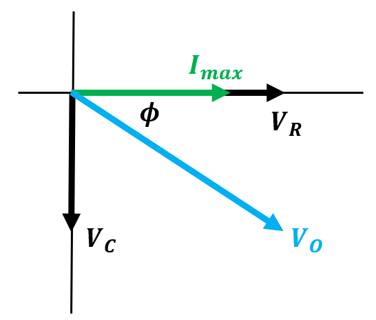
- When drawing phasor diagrams, the axes can be interpreted as follows:
- The horizontal axis represents the resistor
- The positive vertical axis represents the inductor
- The negative vertical axis represents the capacitor
- For an AC circuit in series, the vector sum of these phasors represents the source (applied) voltage.

Wize Concept
We can treat phasors as complex numbers. At any given snapshot in time, the measurements of voltage can be read from the horizontal and vertical components of the phasor.
- If we have a system with resistance and reactances and , the (complex) impedance can be written as follows, where is the imaginary number:
- The magnitude of the complex impedance can be written as follows:
- The source voltage and current of an AC circuit are related by Ohm's Law:
- The phase angle of the impedance is given by:
Watch Out!
The phase angle is the phase difference between the current and the applied (source) voltage.
If , then the voltage is ahead of the current (or the current lags the voltage).
If , then the voltage is behind the current (or the current leads the voltage).
Exam Tip
If an exam problem asks for the phase of the current, you have to flip the sign of the value found with the above phase angle formula. This formula gives the phase of voltage relative to current; flipping the sign gives current relative to voltage.
0:00 / 0:00
RC Circuits (AC)
A purely capacitive AC circuit has a voltage that lags behind the current by . Adding a resistor will modify this behaviour. We call these RC circuits.
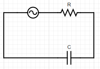
- Consider an RC circuit with a resistance and a capacitance connected in series to an alternating voltage source with frequency and maximum voltage .
- The phasor diagram for this circuit is as follows:
- To find the relationship between current and voltage, we can use the impedance.
- Since there are no inductors, we set .
- This gives the current:
- The phase angle is found similarly:
Wize Concept
For alternating RC circuits, the voltage always lags behind the current, but the lag is less than .
0:00 / 0:00
Example: RC Circuit (AC)
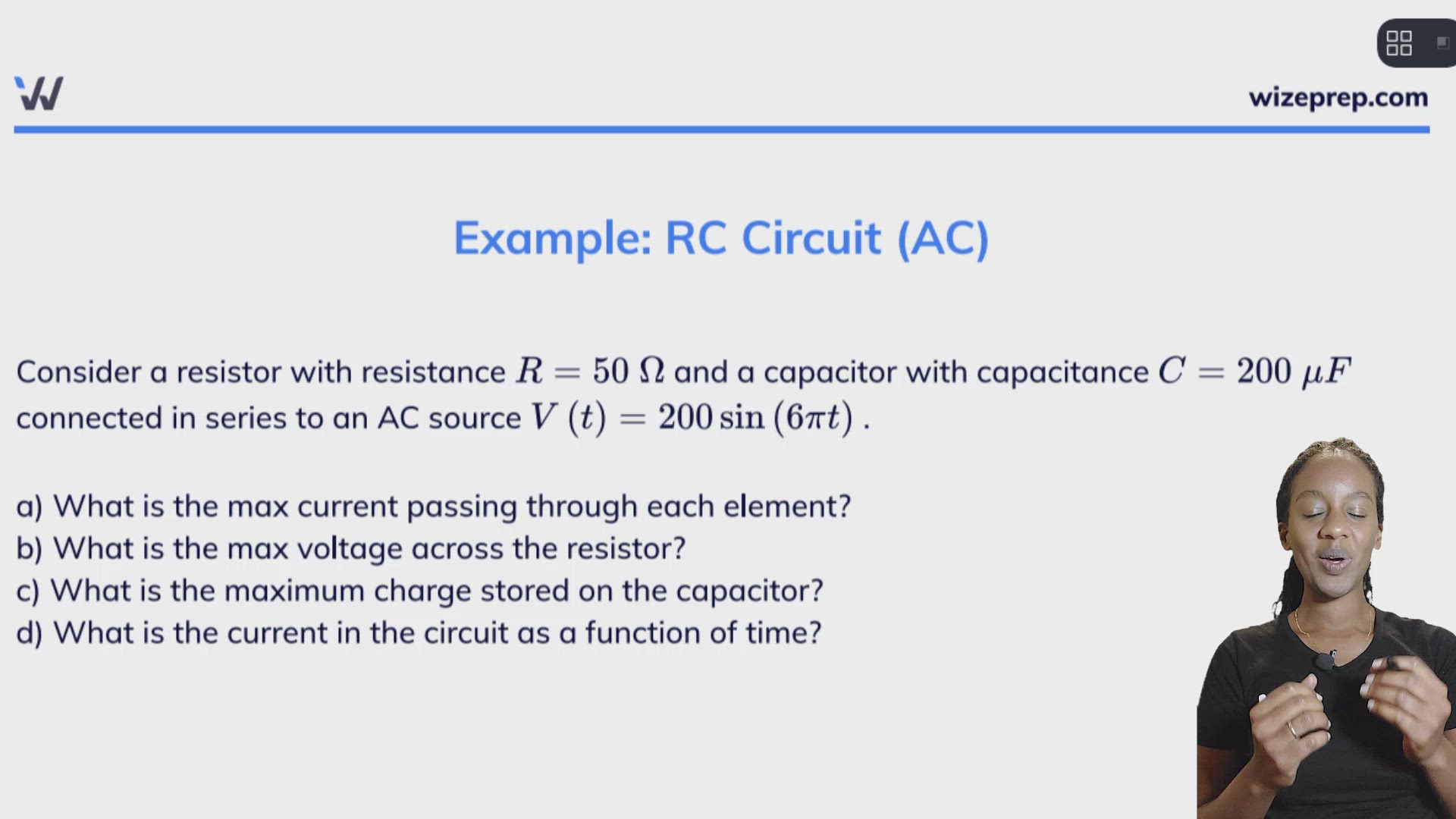
Consider a resistor with resistance and a capacitor with capacitance connected in series to an AC source .
a) What is the max current passing through each element?
b) What is the max voltage across the resistor?
c) What is the maximum charge stored on the capacitor?
d) What is the current in the circuit as a function of time?
We can read from the voltage source that and .
Part a)
Because the circuit is in series, the current is equal through all circuit elements at all times.
We can use Ohm's Law to relate the maximum voltage to the maximum current, but we'll need to find the impedance first:
Using Ohm's Law:
This is the maximum current through each of the circuit elements.
Part b)
The maximum voltage across the resistor is found by multiplying the maximum current by the resistance (Ohm's Law):
Part c)
The formula for charge stored in a capacitor is , so we'll need to find the maximum voltage (with Ohm's Law) before we can find the maximum charge stored.
The maximum voltage across the capacitor is found by multiplying the maximum current by the capacitive reactance (Ohm's Law):
Finding the maximum charge stored:
Part d)
The current will be written in the form . The maximum current was already found in part (a) and the frequency will match the voltage source, so all we need to find is the phase angle:
We know that for RC circuits, the current leads the voltage. We'll flip the sign of this phase angle and substitute it into the formula with the other knowns:
0:00 / 0:00
RL Circuits (AC)
A purely inductive AC circuit has a voltage that leads the current by . Adding a resistor will modify this behaviour. We call these RL circuits.
- Consider an RL circuit with a resistance and an inductance connected in series to an alternating voltage source with frequency and maximum voltage .
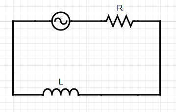
- The phasor diagram for this circuit is as follows:
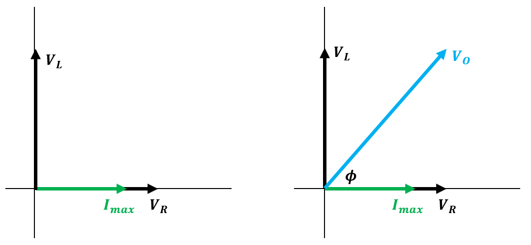
- To find the relationship between current and voltage, we can use the impedance.
- Since there are no capacitors, we set .
- This gives the current:
- The phase angle is found similarly:
Wize Concept
For alternating RL circuits, the voltage always leads the current, but the lead is less than .
Practice: RL Circuit (AC)
Consider a resistor with resistance and two inductors with inductances and . These are all connected in series to an AC voltage source. The source has an RMS voltage of and frequency .
a) What is the maximum current of the circuit?
b) What is the rms voltage across the resistor?
Part a)