
RLC Circuits
An RLC circuit contains an inductor, a resistor and a capacitor.
If we add a resistor to an LC circuit, we make its oscillation a damped oscillation, since the resistor dissipates energy.
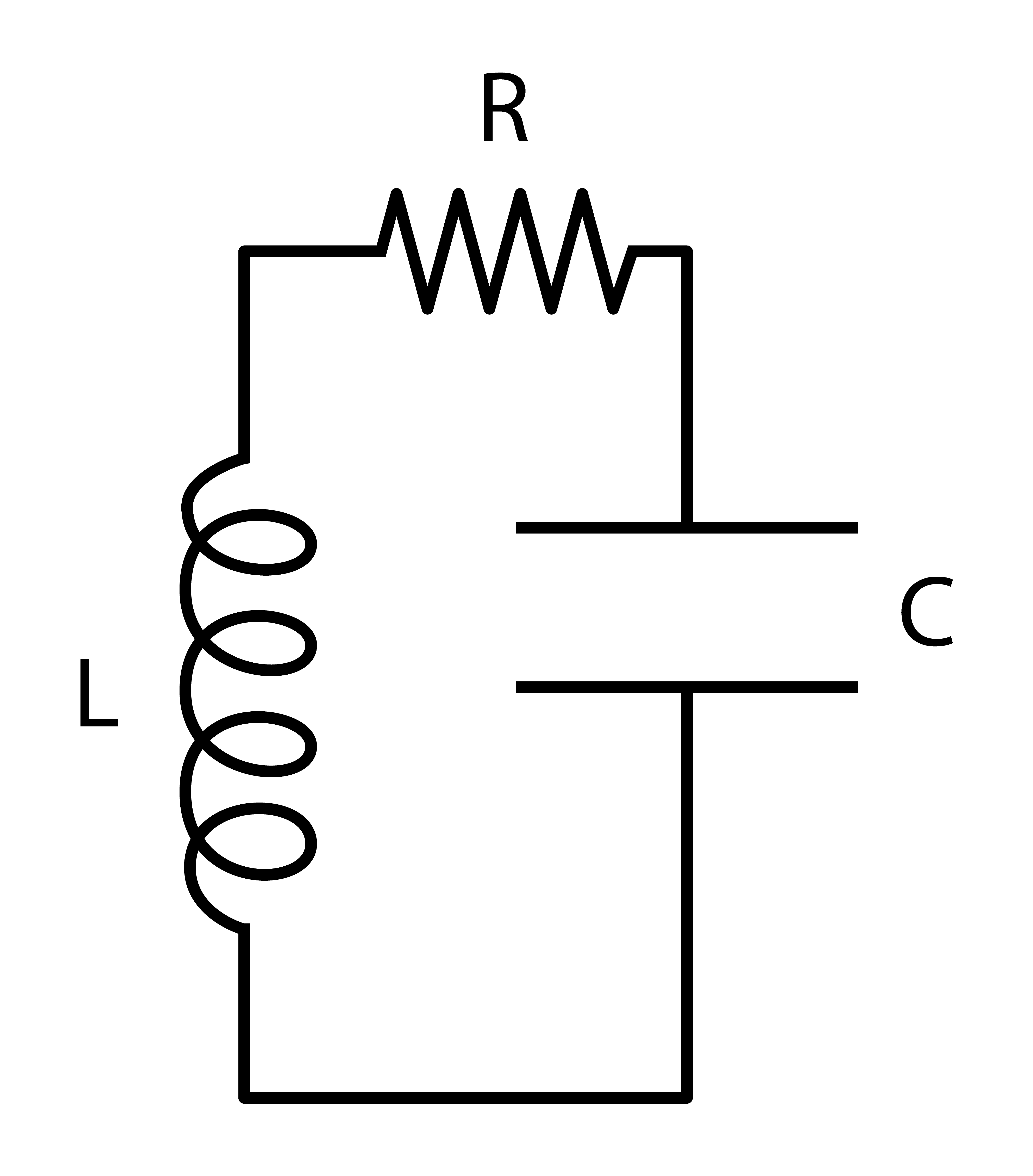
According to Kirchhoff’s voltage rule, we have .
Therefore the charge is:
- is the charge as a function of time
- is the maximum charge
- is the resistance
- is the inductance
- is the phase constant
- is the angular frequency
The angular frequency is given by:
- is the capacitance
We can also write the time constant as:
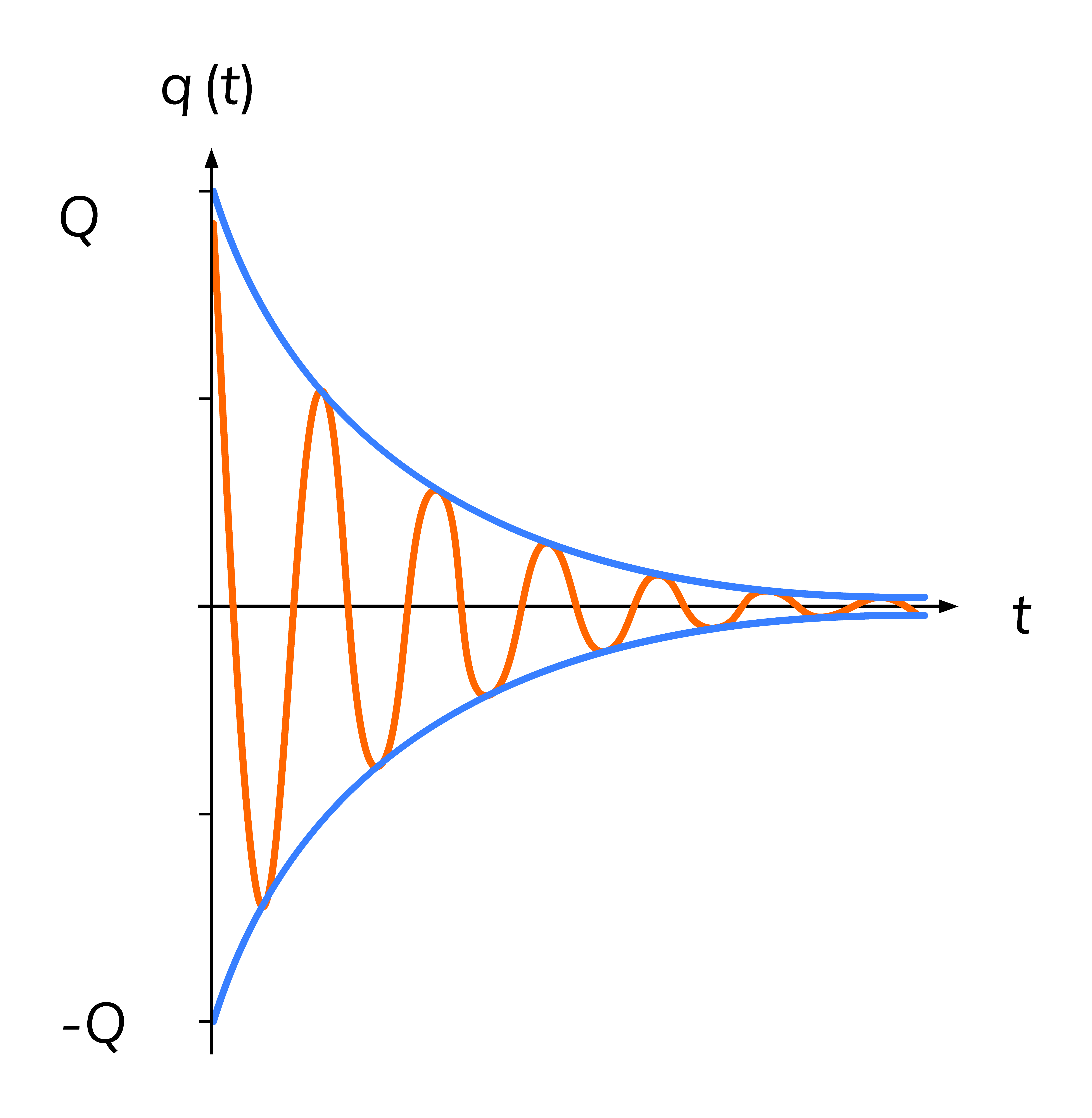
The exponential part of the function is an envelope, while the charge continues to oscillate at frequency . This frequency dictates the behavior of the system:
Case 1: and the oscillations are underdamped, when is small compared to
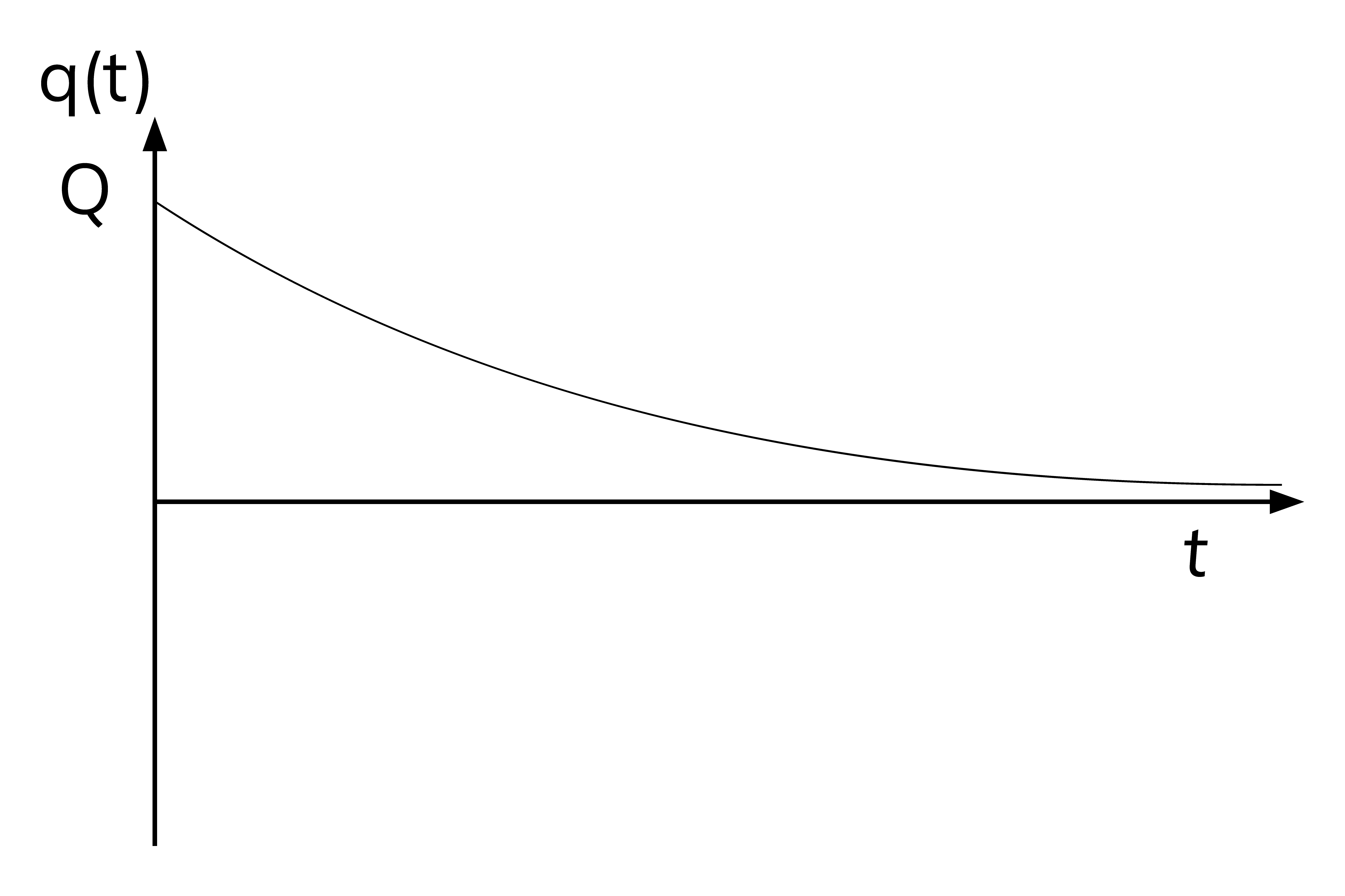
Case 2: and the oscillations are critically damped, when
Case 3: and the oscillations are overdamped case, when is large compared to
Underdamped:
Critical damping:
Overdamping looks like critical damping, except it takes a longer time for the system to reach zero.
Oscillations in Circuits vs. SHM
For all physical quantities involved in simple harmonic motion we have equivalent quantities in LC or RLC circuits.
SHM : LC or RLC Circuits :
position charge
__________________________________________________________________
velocity current
__________________________________________________________________
mass inductance
spring constant capacitance (reciprocal)
__________________________________________________________________
damping constant resistance
__________________________________________________________________
kinetic energy inductor energy
potential energy capacitor energy
__________________________________________________________________
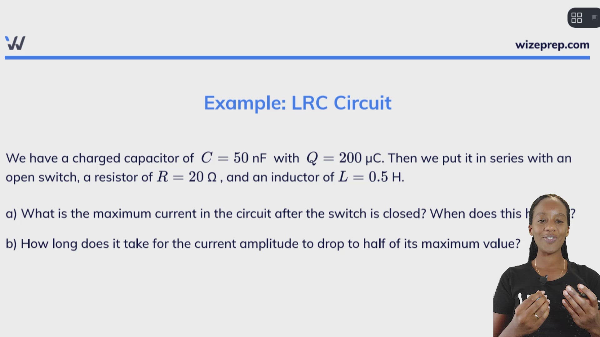
Example: LRC Circuit
We have a charged capacitor of nF with µC. Then we put it in series with an open switch, a resistor of Ω , and an inductor of H.
a) What is the maximum current in the circuit after the switch is closed? When does this happen?
b) How long does it take for the current amplitude to drop to half of its maximum value?
Part a)
We can make the approximation since the first term in the equation is much larger than the second term.
The initial maximum current is given by:
(A)
Initially, the capacitor is fully charged so the current is zero. Then when the charge reaches zero for the first time, the current reaches a maximum for the first time. This happens at a quarter of the period:
(s)
Part b)
The maximum current is described by the "envelope" function:
We need the maximum current to be half of the initial maximum value, which means that and so we have:
Change this to log form and solve for time:
(s)