Wize University Statics Textbook (Master) > Equilibrium of Rigid Body
2D Rigid Body Equilibrium
Rigid Body Equilibrium (2D)
2D Rigid Body - Free Body Diagram (FBD) Practice
Example 1: 2D Rigid Body Equilibrium (Warm Up!)
Example 1: 2D Rigid Body Equilibrium
Example 2: 2D Rigid Body Equilibrium - Part 1 (IMPORTANT!)
Example 2: 2D Rigid Body Equilibrium - Part 2 (IMPORTANT!)
Practice 2: 2D Rigid Body Equilibrium
Practice 1: 2D Rigid Body Equilibrium (Try This - Check your work!)
Practice 3: Spring Practice Problem
2D Solution Method
2D Solution Method
Example: 2D Solution Method
Example: 2D Solution Method
Rigid Body - Practice Questions (2D - Part 1)
Practice: Rigid Body (2D - Part 1)
Quiz: 2D solution Method
Popular Courses
ENGG 130
University of Alberta
CIV100H1
University of Toronto
ENGG 202
University of Calgary
ENGSCI 1022A/B/Y
Western University
PHYS 110
University of Victoria
ENGR 242
Concordia University
ENGR 141
University of Victoria
CE 221
Michigan State University
GENG-1110
University of Windsor
ESM 2104
Virginia Tech
APS160H1
University of Toronto
0:00 / 0:00
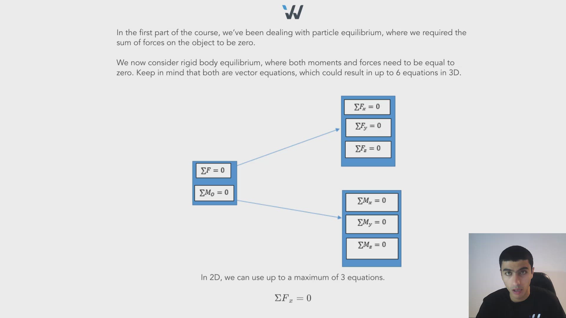
In the first part of the course, we’ve been dealing with particle equilibrium, where we required the sum of forces on the object to be zero.
We now consider rigid body equilibrium, where both moments and forces need to be equal to zero. Keep in mind that both are vector equations, which could result in up to 6 equations in 3D.
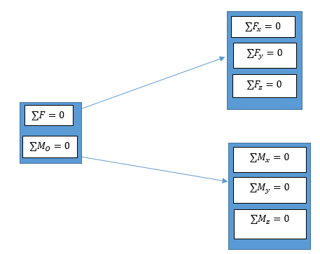
In 2D, we can use up to a maximum of 3 equations.
Bodies are usually attached to a fixed reference (wall, ground, etc.) by some connection. These connections are typically called reaction forces, or support reactions, and are common to be asked on a question. A brief review on these reactions follows on the next two pages.

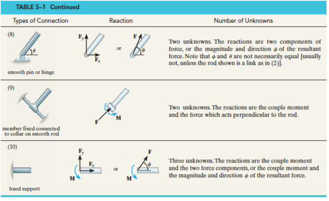


As you may notice, there are many types of support reactions. The key to knowing whether they provide a reaction or not is to ask yourself whether the body would move in a certain direction or rotate about a certain axis.
As always, to solve a system of equations, you can have a maximum number of unknowns equal to the number of equations – up to 3 unknowns in 2D, and up to 6 unknowns in 3D. Therefore, we sometimes simplify the unknown reaction forces to reduce the number of unknowns. Some common simplifications are based around proper alignment – for example:
- A properly aligned bearing exerts two reaction forces, but no moment reactions
- A properly aligned hinge doesn’t exert moment reactions
You will usually be told if you can assume proper alignment of reactions. Another common assumption is “smooth” surfaces (when referring to normal reactions), which allows you to neglect friction.
A note about reaction forces: Not all bodies will have solvable support reactions. This could mean that the support on the body is inadequate, or that there are too many supports – we refer to the body at statically indeterminate.
0:00 / 0:00
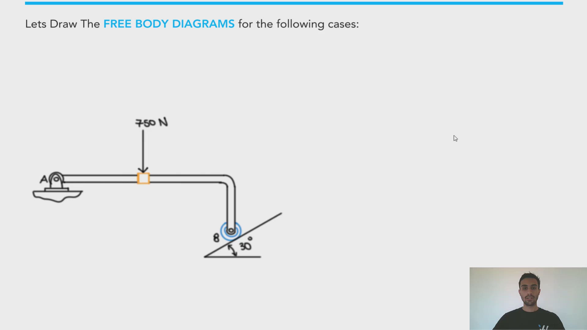
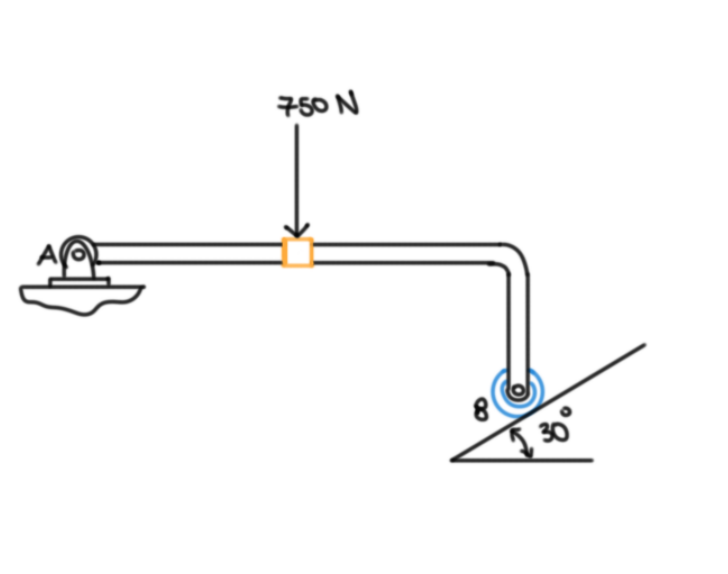
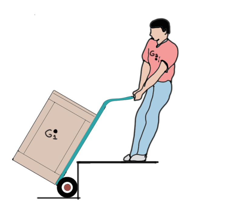
Lets Draw The FREE BODY DIAGRAMS for the following cases:
0:00 / 0:00
Example
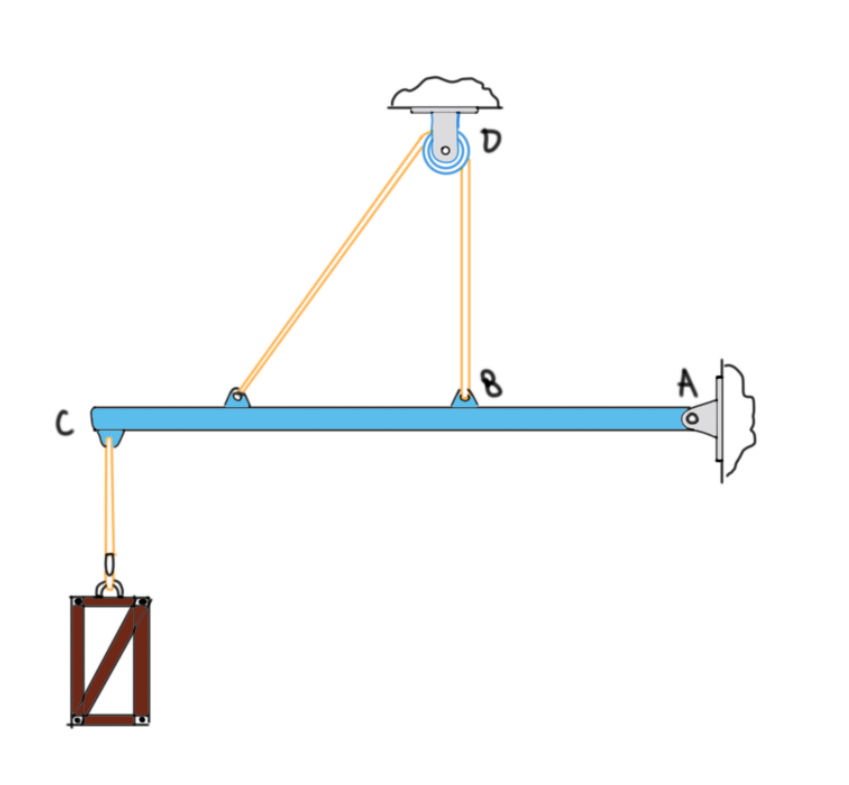
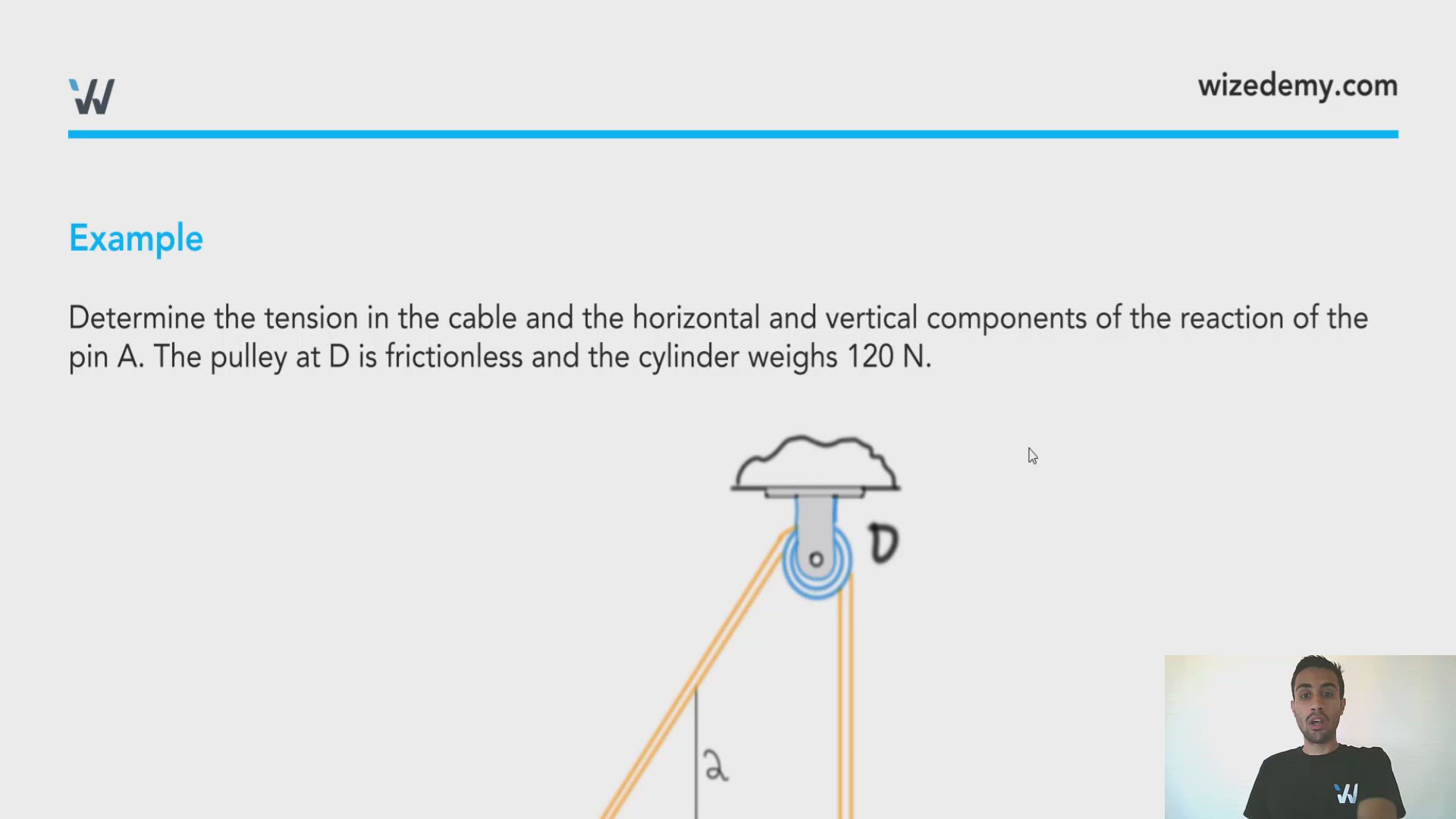
Determine the tension in the cable and the horizontal and vertical components of the reaction of the pin A. The pulley at D is frictionless and the cylinder weighs 120 N.

Solution:
1) Start by drawing Free Body Diagram (FBD) for the Rigid Body,

Take the moment about A to cancel the most unknowns (Ax and Ay) and solve for Tension T,
2) Apply Equilibrium Equations along the x and y directions to solve for the reactions at A,
0:00 / 0:00
Example
Determine the tension in the cable and the horizontal and vertical components of the reaction of the pin A. The pulley at D is frictionless and the cylinder weighs 120 N.
Solution:
1) Start by drawing Free Body Diagram (FBD) for the Rigid Body,
Take the moment about A to cancel the most unknowns (Ax and Ay) and solve for Tension T,
2) Apply Equilibrium Equations along the x and y directions to solve for the reactions at A,
0:00 / 0:00
Example
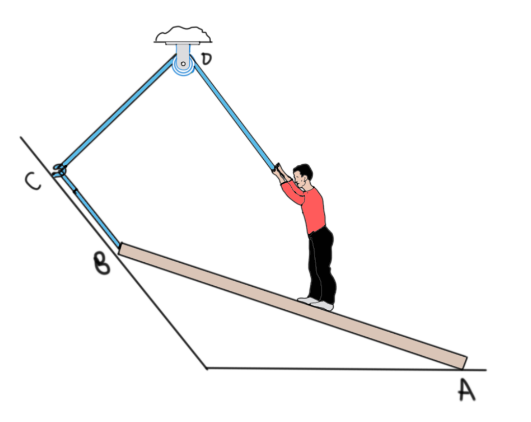
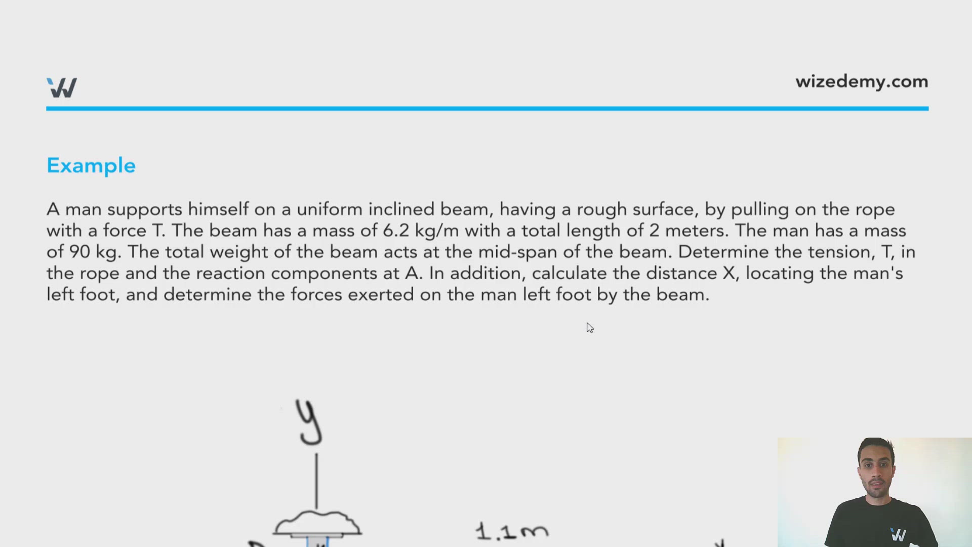
A man supports himself on a uniform inclined beam, having a rough surface, by pulling on the rope with a force T. The beam has a mass of 6.2 kg/m with a total length of 2 meters. The man has a mass of 90 kg. The total weight of the beam acts at the mid-span of the beam. Determine the tension, T, in the rope and the reaction components at A. In addition, calculate the distance X, locating the man's left foot, and determine the forces exerted on the man left foot by the beam.

Solution:
1) Draw Free Body Diagram of the OVERALL SYSTEM – (Man on the Beam - FBD)

Notice from FBD (Man on the beam), we have 4 unknowns, but we can only use 3 equations in 2D. But, we can determine values for Dx and Dy in terms of T.
2) Draw a Free Body Diagram at pulley D only,
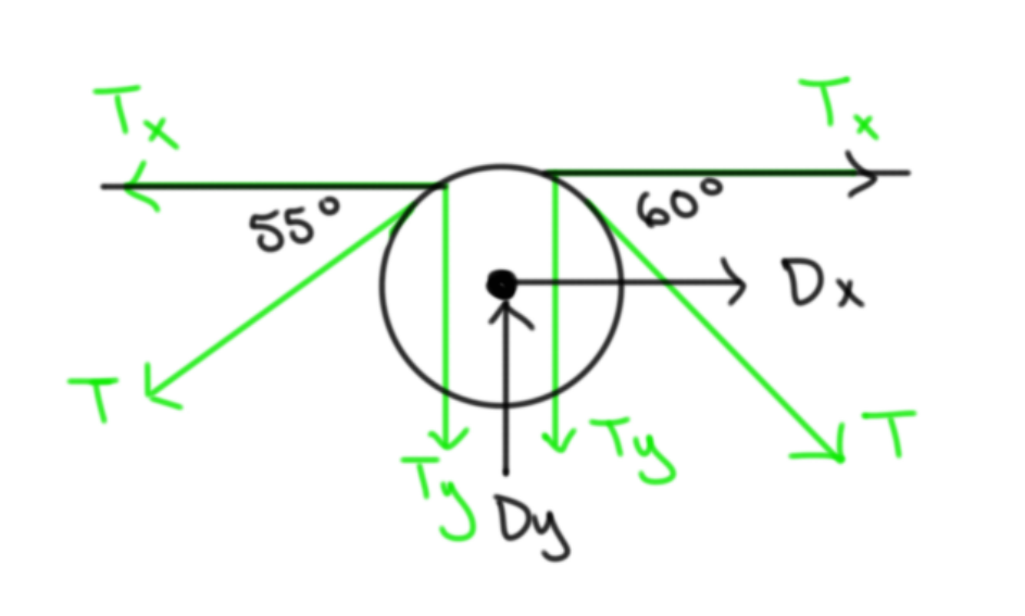
Solve for Dx and Dy using equations of equilibrium,
3) Going back to FBD (Man on the beam), we have values for Dx and Dy in terms of T. Therefore, we have 3 unknowns only now, which is what we want!
Using FBD (Man on the beam), Notice - The perpendicular distance from the weight of the beam to A had to be calculated using cosine function:
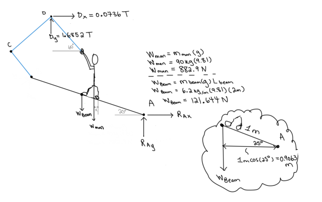
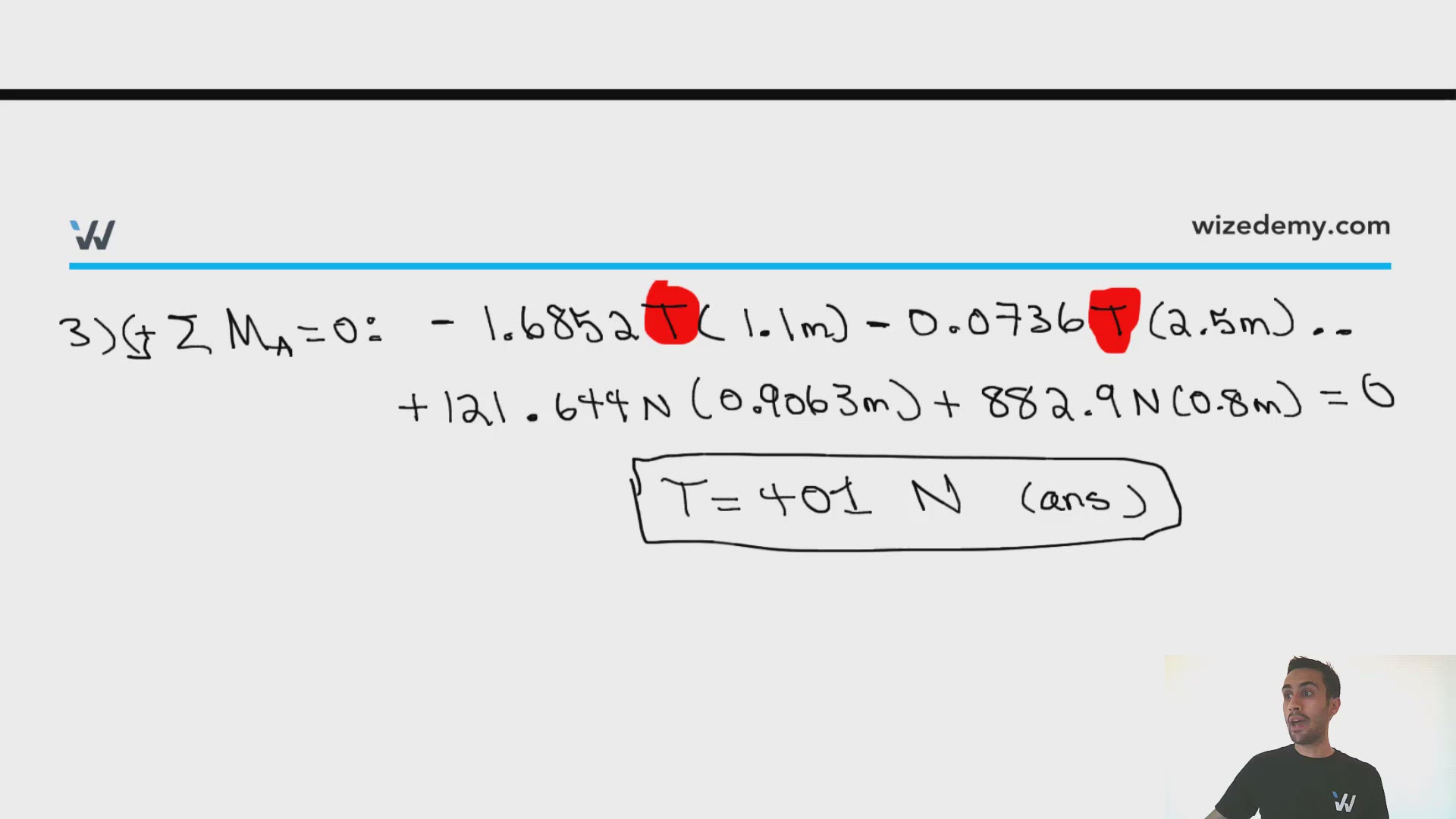
Take the moment about A to eliminate the most amount of unknows (i.e. RAx and Ray),
Sum the forces in the x and y directions to find RAx and RAy,
4) To find the distance X and the forces exerted on the man's left (backfoot), we need to consider the FBD of the man only – FBD (man),
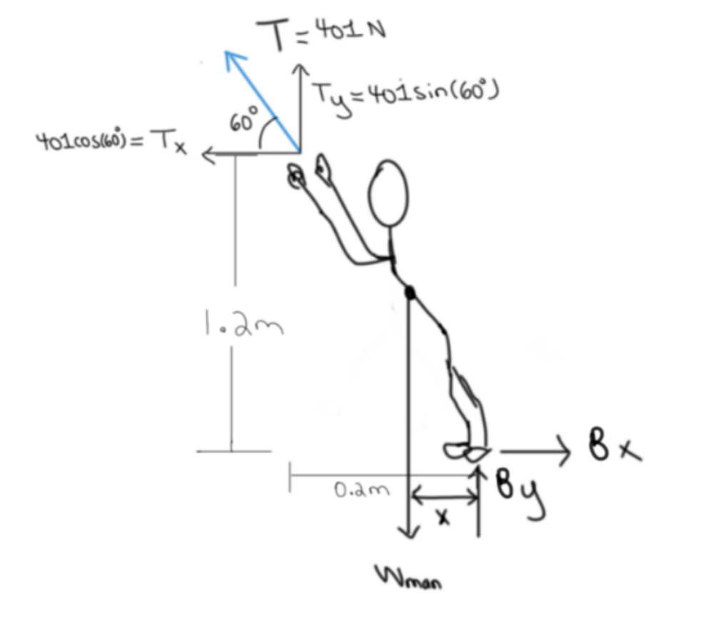
Take the moment about D to eliminate Dx and Dy and solve for x,
To find forces exerted on the man, Dx, and Dy,
0:00 / 0:00
Example
A man supports himself on a uniform inclined beam, having a rough surface, by pulling on the rope with a force T. The beam has a mass of 6.2 kg/m with a total length of 2 meters. The man has a mass of 90 kg. The total weight of the beam acts at the mid-span of the beam. Determine the tension, T, in the rope and the reaction components at A. In addition, calculate the distance X, locating the man's left foot, and determine the forces exerted on the man left foot by the beam.
Solution:
1) Draw Free Body Diagram of the OVERALL SYSTEM – (Man on the Beam - FBD)
Notice from FBD (Man on the beam), we have 4 unknowns, but we can only use 3 equations in 2D. But, we can determine values for Dx and Dy in terms of T.
2) Draw a Free Body Diagram at pulley D only,
Solve for Dx and Dy using equations of equilibrium,
3) Going back to FBD (Man on the beam), we have values for Dx and Dy in terms of T. Therefore, we have 3 unknowns only now, which is what we want!
Using FBD (Man on the beam), Notice - The perpendicular distance from the weight of the beam to A had to be calculated using cosine function:
Take the moment about A to eliminate the most amount of unknows (i.e. RAx and Ray),
Sum the forces in the x and y directions to find RAx and RAy,
4) To find the distance X and the forces exerted on the man's left (backfoot), we need to consider the FBD of the man only – FBD (man),
Take the moment about D to eliminate Dx and Dy and solve for x,
To find forces exerted on the man, Dx, and Dy,
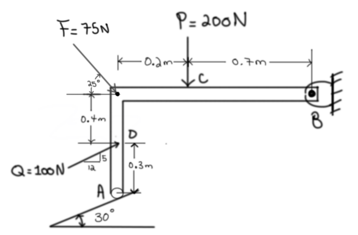
The L-shaped bracket illustrated below is acted upon by forces P, F, and Q.
a) Draw the free body diagram for this bracket.
b) Determine the equivalent force-couple system at B.
c) Calculate the reactions at A and B.
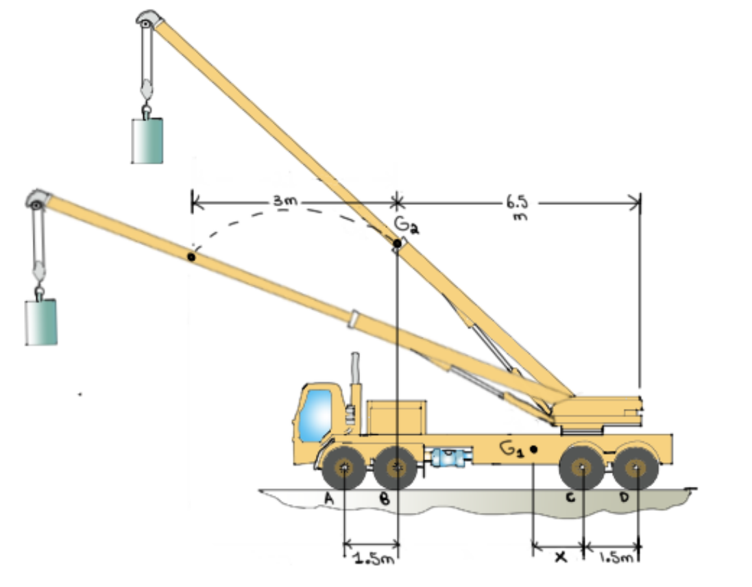
The mobile crane consists of a crane truck and boom, with centers of gravity G1 and G2, respectively. With the boom lifted up, the rear axle loads (normal reactions) at C and D are 225 kN each, and the front axle loads at A and B are 185 kN each. When the boom is down in position, the rear axle loads are decreased by 35 kN. Determine the weight of the crane truck and the mass of the boom, as well as the distance x.
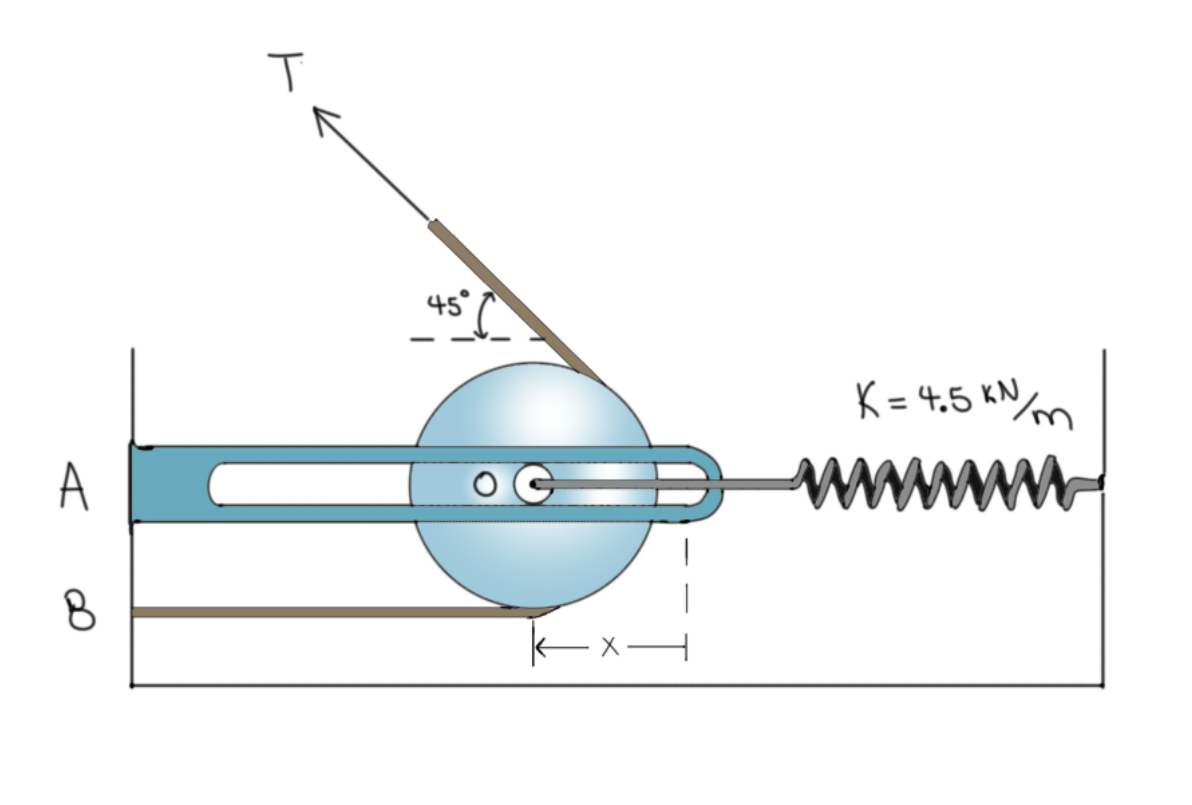
The spring of modulus k = 4.5 kN/m is loaded by a tension force of 45 N when the disc center O is in the rightmost position (at x = 0). Determine the tension T required to position the disc center at x = 170 mm. For that position, calculate the distance OA if the moment reaction at the fixed support at A is 72.5 N-m. The mass of the disc is 3.5 kg.
0:00 / 0:00
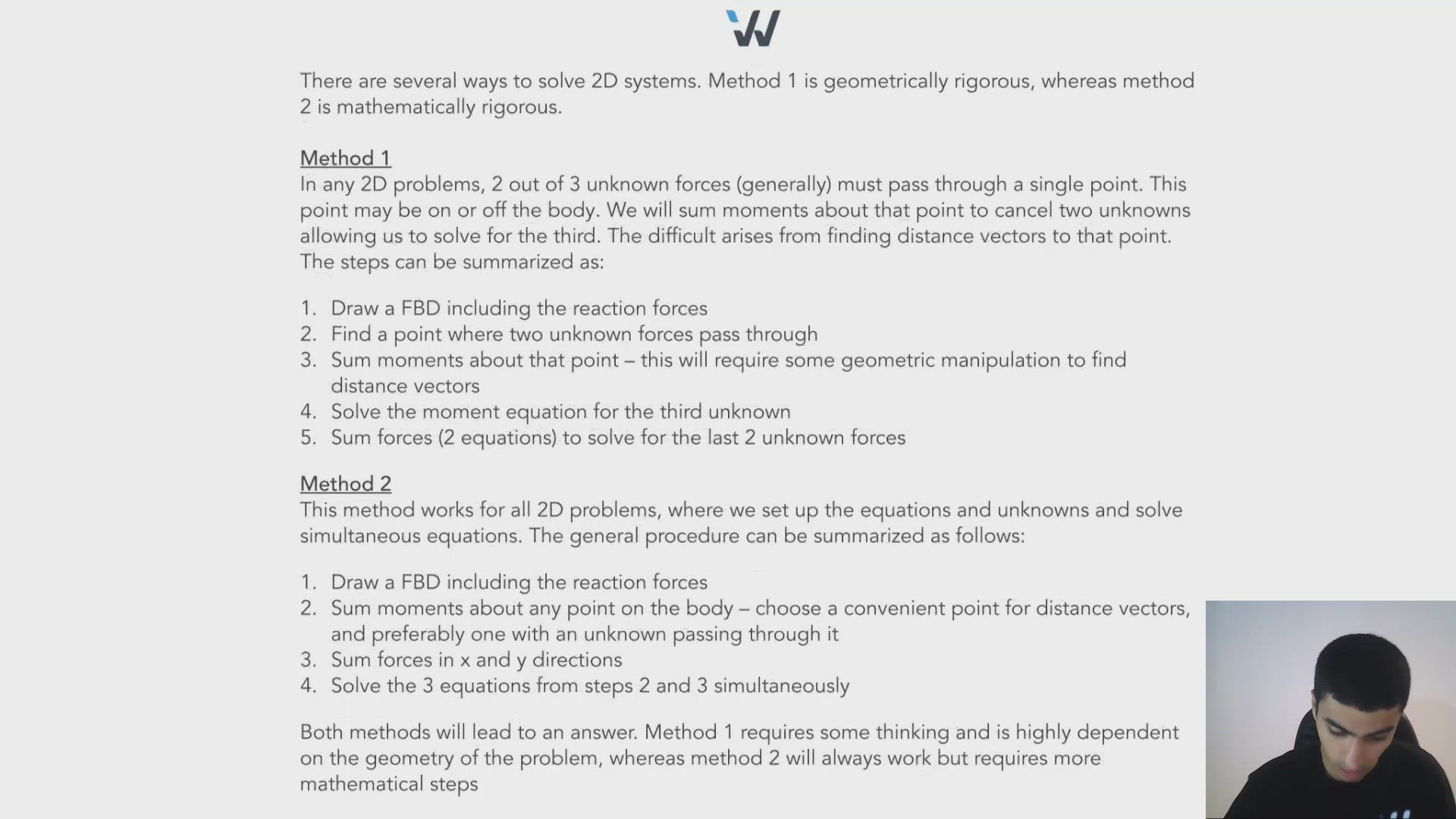
There are several ways to solve 2D systems. Method 1 is geometrically rigorous, whereas method 2 is mathematically rigorous.
Method 1
In any 2D problems, 2 out of 3 unknown forces (generally) must pass through a single point. This point may be on or off the body. We will sum moments about that point to cancel two unknowns allowing us to solve for the third. The difficult arises from finding distance vectors to that point. The steps can be summarized as:
- Draw a FBD including the reaction forces
- Find a point where two unknown forces pass through
- Sum moments about that point – this will require some geometric manipulation to find distance vectors
- Solve the moment equation for the third unknown
- Sum forces (2 equations) to solve for the last 2 unknown forces
Method 2
This method works for all 2D problems, where we set up the equations and unknowns and solve simultaneous equations. The general procedure can be summarized as follows:
- Draw a FBD including the reaction forces
- Sum moments about any point on the body – choose a convenient point for distance vectors, and preferably one with an unknown passing through it
- Sum forces in x and y directions
- Solve the 3 equations from steps 2 and 3 simultaneously
Both methods will lead to an answer. Method 1 requires some thinking and is highly dependent on the geometry of the problem, whereas method 2 will always work but requires more mathematical steps
0:00 / 0:00
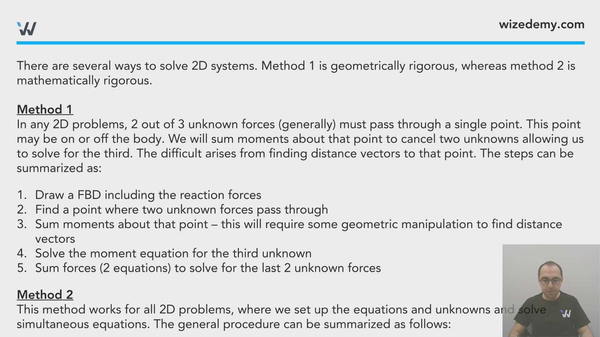
There are several ways to solve 2D systems. Method 1 is geometrically rigorous, whereas method 2 is mathematically rigorous.
Method 1
In any 2D problems, 2 out of 3 unknown forces (generally) must pass through a single point. This point may be on or off the body. We will sum moments about that point to cancel two unknowns allowing us to solve for the third. The difficult arises from finding distance vectors to that point. The steps can be summarized as:
- Draw a FBD including the reaction forces
- Find a point where two unknown forces pass through
- Sum moments about that point – this will require some geometric manipulation to find distance vectors
- Solve the moment equation for the third unknown
- Sum forces (2 equations) to solve for the last 2 unknown forces
Method 2
This method works for all 2D problems, where we set up the equations and unknowns and solve simultaneous equations. The general procedure can be summarized as follows:
- Draw a FBD including the reaction forces
- Sum moments about any point on the body – choose a convenient point for distance vectors, and preferably one with an unknown passing through it
- Sum forces in x and y directions
- Solve the 3 equations from steps 2 and 3 simultaneously
Both methods will lead to an answer. Method 1 requires some thinking and is highly dependent on the geometry of the problem, whereas method 2 will always work but requires more mathematical steps
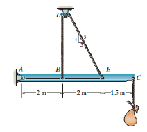
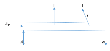
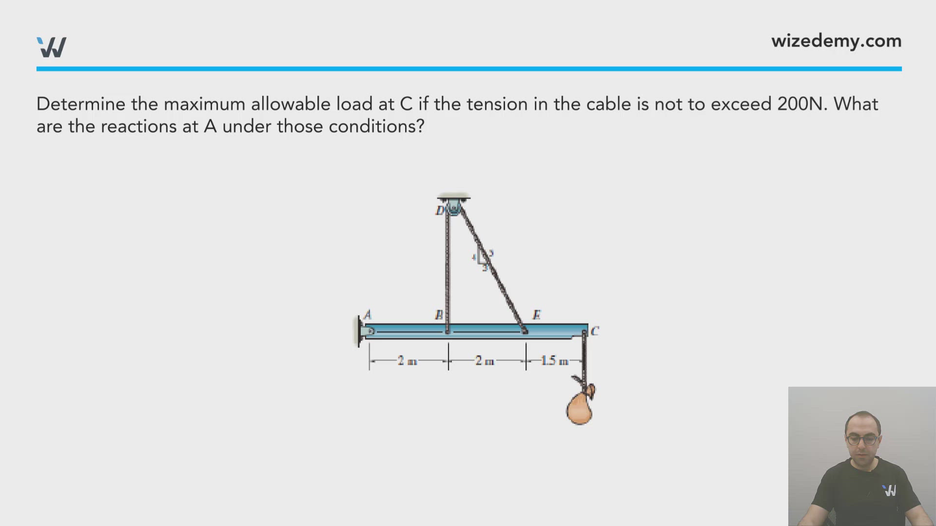
Determine the maximum allowable load at C if the tension in the cable is not to exceed 200N. What are the reactions at A under those conditions?
0:00 / 0:00
Determine the maximum allowable load at C if the tension in the cable is not to exceed 200N. What are the reactions at A under those conditions?

Mark Yourself Question
- Grab a piece of paper and try this problem yourself.
- When you're done, check the "I have answered this question" box below.
- View the solution and report whether you got it right or wrong.
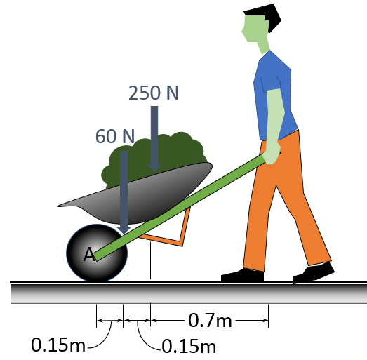
a) Determine the lifting force needed and the reaction at the wheel A to lift the wheel barrel.
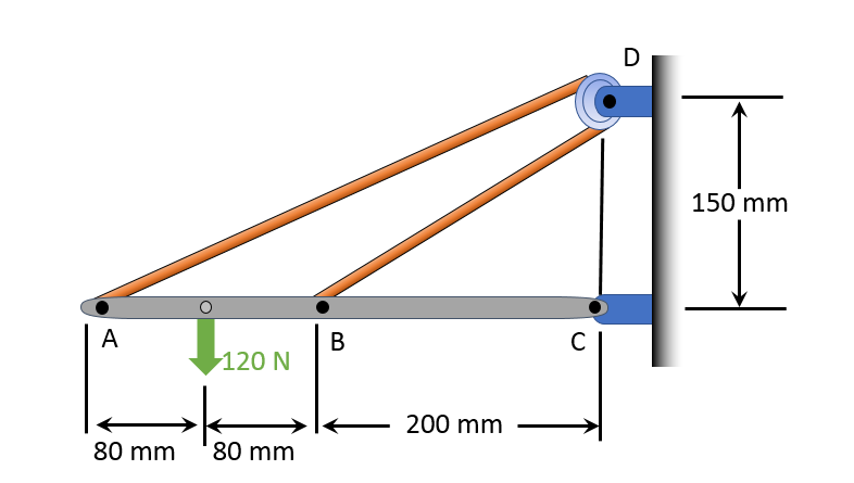
b) Determine the tension in the continuous cable ADB, and the reactions at the pin at C.
Mark Yourself Question
- Grab a piece of paper and try this problem yourself.
- When you're done, check the "I have answered this question" box below.
- View the solution and report whether you got it right or wrong.
a) Determine the lifting force needed and the reaction at the wheel A to lift the wheel barrel.
b) Determine the tension in the continuous cable ADB, and the reactions at the pin at C.
Quiz: 2D solution Method
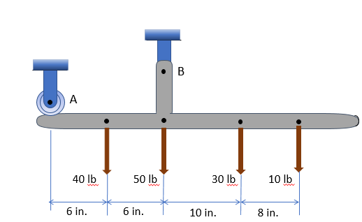
Determine the reaction forces at A and B.
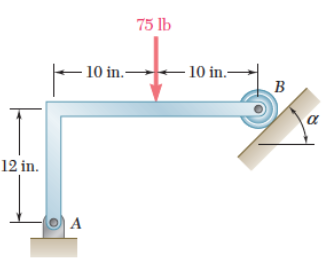
Determine the reaction forces at A and B. Take α =
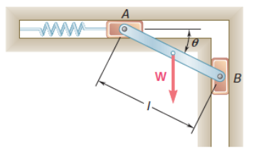
The spring is unstreched when θ = 0. If W = 10N, determine the value of θ. Take l = 1m, and k =100N/m.
The bar of negligible weight is supported by two springs at A and B and is initially horizontal before the load is applied. Once the 800N load is applied, the bar is pushed down, but remains horizontal. Determine the relationship between the two spring constants kA and kB.
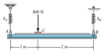
The relationship is: Enter the value of x
The following ramp has a weight of 20 kN acting at point G. Determine the minimum tension needed to start lifting the ramp.