Wize University Statics Textbook (Master) > Internal Forces
Shear and Moment Diagrams
Method 1 - using Method of Sections
Example 1: Drawing Shear and Moment Diagrams (DO THIS!)
Example 2: Drawing Shear and Moment Diagrams
Example: Internal Forces Graphs 1
Example: Internal Forces Graphs 2
Example 2: Internal Forces as a Function of x (MUST KNOW!)
Practice 1: Drawing Shear and Moment Diagrams (DO THIS!)
Practice 2: Drawing Shear and Moment Diagrams (DO THIS!)
Example 2 - Part 1: ENGG 130
Example 2 - Part 2: ENGG 130
Method 2 - using Shortcuts
Practice 3 (IMPORTANT - EXAM LIKE!) : Drawing Shear and Moment Diagrams
Practice: Internal Forces (Graphical)
Practice 3: Internal Forces as a Function of x. (MUST KNOW!)
Practice 4: Internal Forces as a Function of x. (MUST KNOW!)
Practice 5: Internal Forces as a Function of x. (MUST KNOW!)
Popular Courses
ENGG 130
University of Alberta
CIV100H1
University of Toronto
ENGG 202
University of Calgary
ENGSCI 1022
Western University
GNG 1105
University of Ottawa
ENGR 242
Concordia University
ENGR 141
University of Victoria
CE 221
Michigan State University
GENG-1110
University of Windsor
ESM 2104
Virginia Tech
APS160H1
University of Toronto

0:00 / 0:00
Method 1 (apply equations of equilibrium to 'sections' of the beam):
1) Every time something changes on the beam – split it into different sections
2) Look at each section individually, and represent the internal forces at any point using a function of some arbitrary distance ‘x’ from the edge of the beam
3) Combine the shear force and bending moment functions from all beam segments, to generate 2 graphs of shear force and bending moment as a function of position on the beam.
* This takes longer, but has the mathematical foundation for the drawn diagram WHEN YOUR INSTRUCTOR requires that you "SHOW YOUR WORK". This also is how you determine the SHEAR or MOMENT as a "function of x".
EXAMPLE....


0:00 / 0:00
Draw the shear and moment diagrams for the beam.

1) Find Reactions,
2) Draw Shear and Moment Diagram,


0:00 / 0:00
Example
The beam ABCDE located in an existing structure will be subject to new increased loads shown below. Member EFG is attached rigidly to the beam at E.
a) Draw the shear and moment diagrams for the beam indicating the values at points A, B, C, D, and E as well as any potential local maxima and minima.
b) The beam is made of a solid rectangular cross-section with a circular hole for electrical conduits. It is constructed of Grade 6061-T4 aluminum with a yield stress of 110 MPa. Determine if the beam is safe to carry the new loads. The required load factor of flexure is 1.8. The second moment of area for the circular areas is where r is the radius of the circle.

a)
Solve for Reactions,

Draw shear and moment diagram,

b)
Size the member using the maximum value for the moment from the diagram for bending about the x-axis.
Mmax-x= 346.5 kN-m
Second Moment of Area ( Moment of Interia) about the X-axis,


0:00 / 0:00
Draw the shear force and bending moment diagram for the following beam


RA= 2/3 P
Rc = 1/3 P
o < x < L/3

L/3<x<2/3L


0:00 / 0:00
Draw the shear force and bending moment diagram for the following beam

Rc = 104
RB = 36
DRAWING:

FBD:

V/M Diagram:


0:00 / 0:00
Example
Determine the internal shear and moment in the beam as a function of x throughout the beam.

Internal Shear and Moment:

Internal Shear and Moment:

Mark Yourself Question
- Grab a piece of paper and try this problem yourself.
- When you're done, check the "I have answered this question" box below.
- View the solution and report whether you got it right or wrong.
Draw the shear and moment diagrams for the beam.

Mark Yourself Question
- Grab a piece of paper and try this problem yourself.
- When you're done, check the "I have answered this question" box below.
- View the solution and report whether you got it right or wrong.
Practice
Draw the shear and moment diagrams for the beam.


0:00 / 0:00
Example
a) The beam ABCDE located in an existing structure will be subject to new increased loads shown below. Member EFG is attached rigidly to the beam at E. Draw the shear and moment diagrams for the beam indicating the values at points A, B, C, D, and E as well as any potential local maxima and minima.
b) The beam is made of a solid rectangular cross-section with a circular hole for electrical conduits. determine the moment of inertia about the x-axis passing through the centroid of the section.
a)
Solve for Reactions,
Draw shear and moment diagram,

b)
Second Moment of Area ( Moment of Interia) about the X-axis,


0:00 / 0:00
Example
a) The beam ABCDE located in an existing structure will be subject to new increased loads shown below. Member EFG is attached rigidly to the beam at E. Draw the shear and moment diagrams for the beam indicating the values at points A, B, C, D, and E as well as any potential local maxima and minima.
b) The beam is made of a solid rectangular cross-section with a circular hole for electrical conduits. determine the moment of inertia about the x-axis passing through the centroid of the section.
a)
Solve for Reactions,
Draw shear and moment diagram,
b)
Second Moment of Area ( Moment of Interia) about the X-axis,

0:00 / 0:00
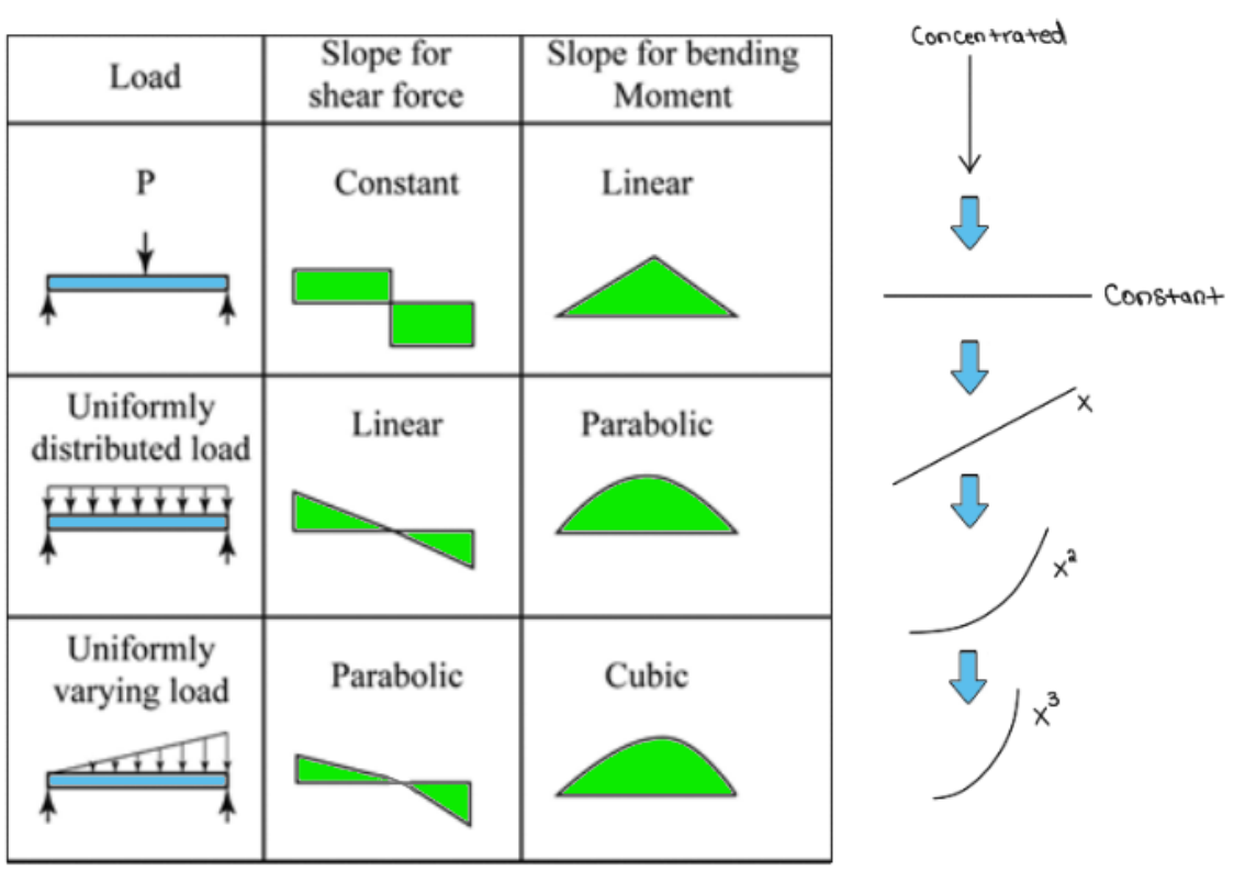
Method 2 (using shortcuts):
The second method is typically easier to do, you just need to follow some simple guidelines:
1) The shear force diagram is the integral of the intensity function on the beam.
2) Point loads or concentrated loads cause a ‘jump’ in the shear force diagrams that is equal to the magnitude of the force in the same direction as the force
3) The bending moment diagram is the integral of the shear force diagram
4) External couple moments cause ‘jumps’ in the bending moment diagram that is equal to the magnitude of the moment, with clockwise being an upward ‘jump’
* This method is much faster. But MAKE SURE your instructor allows this solution as it doesn't "SHOW SUPPORTING WORK". I USE THIS METHOD to "quickly check" my METHOD 1 solutions or PREDICT what my graphs 'should' look like.
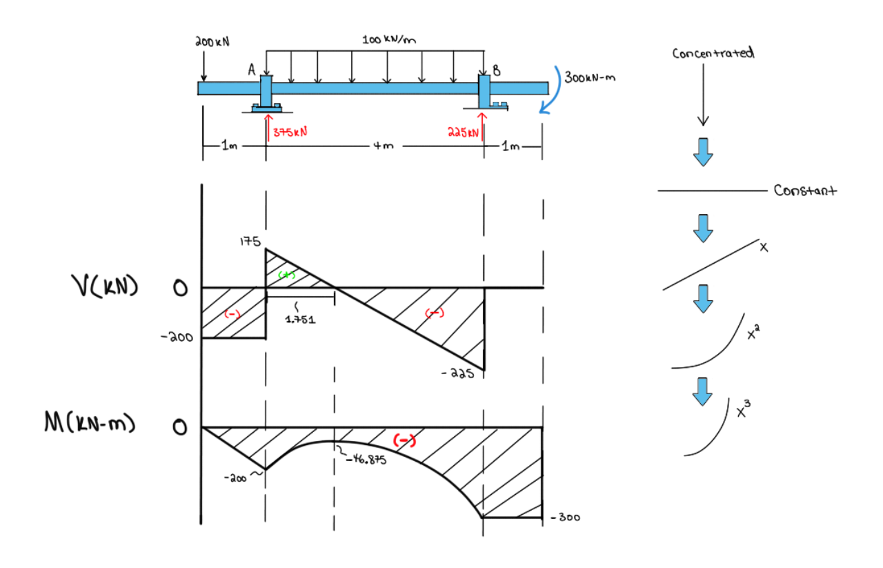
Let's Examine the Following Shear and Moment Diagram Together!
Practice
The 7.5 m-long timber floor beam, having a square cross-section, is to be designed to carry the loads shown. Because only 5 m-long timbers are available, the beam is to be fabricated from two pieces connected together by a nailed joint, D. You are required to:
(a) In the space provided, draw the shear force and bending moment diagrams for the beam indicating the values at points A, B, and C, and any potential local maxima and minima.
(b) If wood has a strength of 30 MPa, in both tension and compression, determine the required size, a, for the beam such that it can safely carry the floor loads. The load factor for timber in bending is l .67.
( c) Determine the distance b for the most advantageous position of the joint D, knowing that nailed joints are strong in shear but weak in bending.

Mark Yourself Question
- Grab a piece of paper and try this problem yourself.
- When you're done, check the "I have answered this question" box below.
- View the solution and report whether you got it right or wrong.
Draw the shear force and bending moment diagram for the following beam

Mark Yourself Question
- Grab a piece of paper and try this problem yourself.
- When you're done, check the "I have answered this question" box below.
- View the solution and report whether you got it right or wrong.
Practice
Determine the internal shear and moment in the beam as a function of x throughout the beam.

Mark Yourself Question
- Grab a piece of paper and try this problem yourself.
- When you're done, check the "I have answered this question" box below.
- View the solution and report whether you got it right or wrong.
Determine the shear and moment throughout the beam a function of x within the region .
