Popular Courses
ENGG 130
University of Alberta
CIV100H1
University of Toronto
ENGG 202
University of Calgary
ENGSCI 1022A/B/Y
Western University
GNG 1105
University of Ottawa
ENGR 242
Concordia University
ENGR 141
University of Victoria
CE 221
Michigan State University
GENG-1110
University of Windsor
ESM 2104
Virginia Tech
APS160H1
University of Toronto
0:00 / 0:00
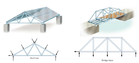
TRUSSES are a major component of the section on the “Structural Analysis" section of the course. The majority are PLANAR (in a plane) trusses, which are basically 2D trusses used for Roofs and Bridges. There are also SIMPLE trusses that are, well, more simple in design and composed of "triangles".
Trusses are made up of smaller pieces (called MEMBERS) which are connected at their ends by pins (at a JOINT)
External Loading is applied at the joints
Assumptions for analysis and design:
1) Trusses are lightweight structures designed to carry large loads.
2) Each truss member ACTS as a TWO FORCE MEMBERS joined by "smooth" pins at their ends at JOINTS.
3) ALL LOADING is applied / occurs at the JOINTS.
4) Force in each member will be directed along the axis of the member (so sum F's = 0, and NO MOMENT setup).
5) The weight of the members is negligible (compared to loading on truss)
6) The resultant forces on Members are either in TENSION (elongation/stretch), or COMPRESSION (shortening/squish), or the force in the member is ZERO (zero force member).
HOW TO APPROACH TRUSSES:
We will look at the TWO METHODS for solving for forces in trusses in the next section (MOJ, MOS).
REMEMBER: when it comes to truss questions, there are three things they usually ask for:
- Reaction Forces – > use external analysis
- Forces in all members – > use "method of joints" MOJ
- Forces in a few or specific (2-3) members – > "method of sections" (MOS)
All truss questions should begin with an external analysis.
- Draw the FBD of the overall truss, include support forces
2. Find (solve for) support reactions (*you may not need them, but worth doing)
Exception: when using method of sections, if you can make a cut that doesn’t include reaction forces, then an external force balance is not necessary.
3. Identify any ZERO FORCE members (if not positive, leave them in)
4. Decide which method you will use (review in NEXT SECTION)
- Method of joints (MOJ): when need F in many / all members
-or- for when interested in members near the edge of the structure.
- Method of sections (MOS): when need F in just a few members (typically 3 or less) near the middle of the structure.
- Combination: you may need to combine both methods to solve, but this can be rare.
2-Force Members:
2 force members are the most common, and most useful to identify.
> can have many forces acting on them, as long as the forces act only on two points (typically at the joints).
> cannot have a moment or couple moment acting on it
> can be a bar, bracket, or other shape that has two joints or connection points.
3 Force Members
3 force members are sometimes useful, but you’re usually not required to know them. Similar to 2 force members, 3 force members could have multiple forces acting on them, as long as they are only applied in 3 locations only, with no couple moments present. This typically occurs in trusses that have forces acting in their mid-section, which aren't very common, but are more applicable in frames and machines questions.
The resultant force from the 3 points on the member could have 2 cases: either all 3 forces are parallel, or they all pass through the same point (which could be on or off the body)
It is important to note that 2 and 3 force members only refers to the number of locations on the body which the forces act, and doesn’t refer to the total number of forces acting on the body.
0:00 / 0:00
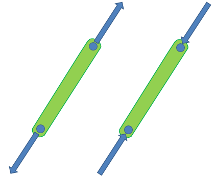
2 Force Members
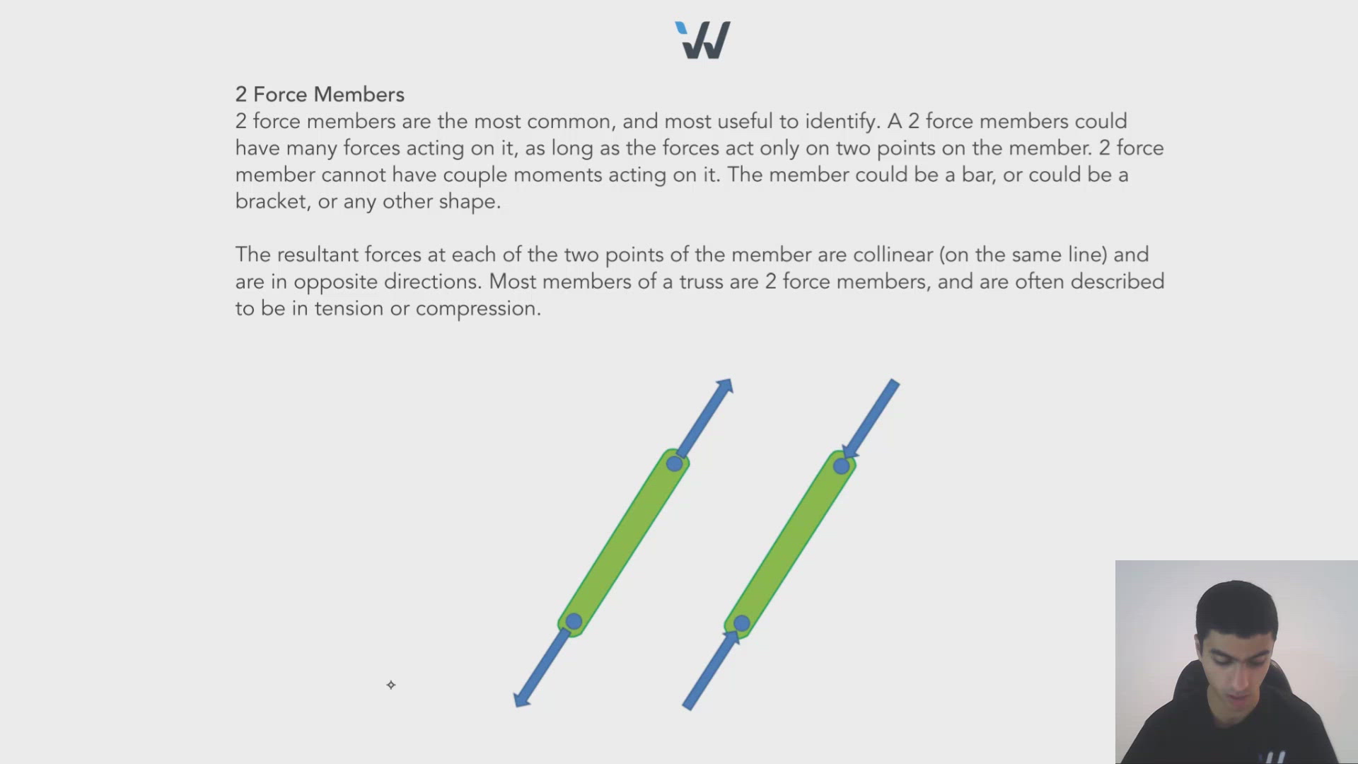
2 force members are the most common, and most useful to identify. A 2 force members could have many forces acting on it, as long as the forces act only on two points on the member. 2 force member cannot have couple moments acting on it. The member could be a bar, or could be a bracket, or any other shape.
The resultant forces at each of the two points of the member are collinear (on the same line) and are in opposite directions. Most members of a truss are 2 force members, and are often described to be in tension or compression.
3 Force Members
3 force members are sometimes useful, but you’re usually not required to know them. Similar to 2 force members, 3 force members could have multiple forces acting on them, as long as they are only applied in 3 locations only, with no couple moments present. This typically occurs in trusses that have forces acting in their mid-section, which aren't very common, but are more applicable in frames and machines questions.
The resultant force from the 3 points on the member could have 2 cases: either all 3 forces are parallel, or they all pass through the same point (which could be on or off the body)
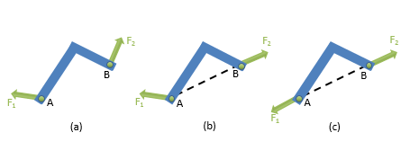
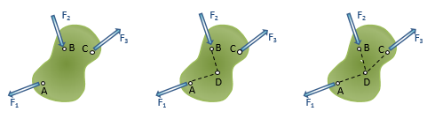
It is important to note that 2 and 3 force members only refers to the number of
locations on the body which the forces act, and doesn’t refer to the total number of
forces acting on the body.

0:00 / 0:00
0 Force Members
0 force members are typically members of a truss that have zero force within them. These members are present for redundancy, AS BACKUP or TO SUPPORT LONG MEMBERS that MUST SPAN A LARGE DISTANCE or there "just in case" the loading changes or things go wrong and start breaking, or to allow for alternative loading conditions. The key point is that just because a member is a zero-force member under certain loading conditions, that doesn’t make it zero force member under all loading conditions.
There are two conditions that make a member a zero force member:
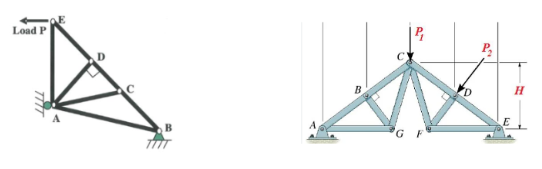
- CONDITION 1 > Two members that are not collinear FORM A JOINT, with nothing else at that joint (ie. NO LOADING or SUPPORT REACTION AT THE JOINT!!!!!
>>>>> Both members are zero force members.
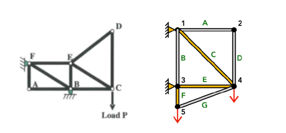
2. CONDITION 2 > If Three members form a TRUSS JOINT, for which two are collinear (in a line), and the third isn’t, and there’s nothing else at that joint (ie. NO LOADING or SUPPORT REACTION)
>>>> the third member is a zero force member.
Wize Tip
If you are not sure if a member is a ZERO FORCE member, then leave it in the analysis.
IF it IS a ZFM, then it will = 0.
General procedure for analysis of zero force members:
- Replace all external forces and reaction forces by “members or loadings”
- Start at one end of the truss, and analyze one joint at a time looking for either of the above conditions to be satisfied. Label those members as zero-force members.
- Return to the beginning, and repeat – because some members may have become zero force members after canceling out other members.
0:00 / 0:00
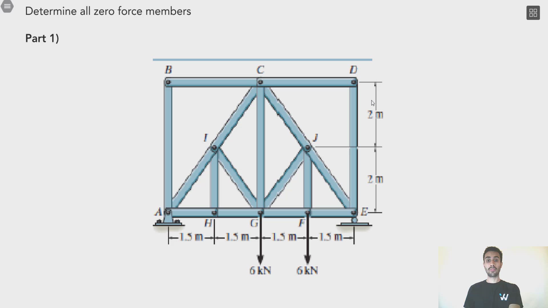
Determine all zero force members
Part 1)
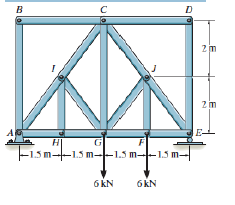
AB, BC, CD, DE, HI, IG
Part 2)
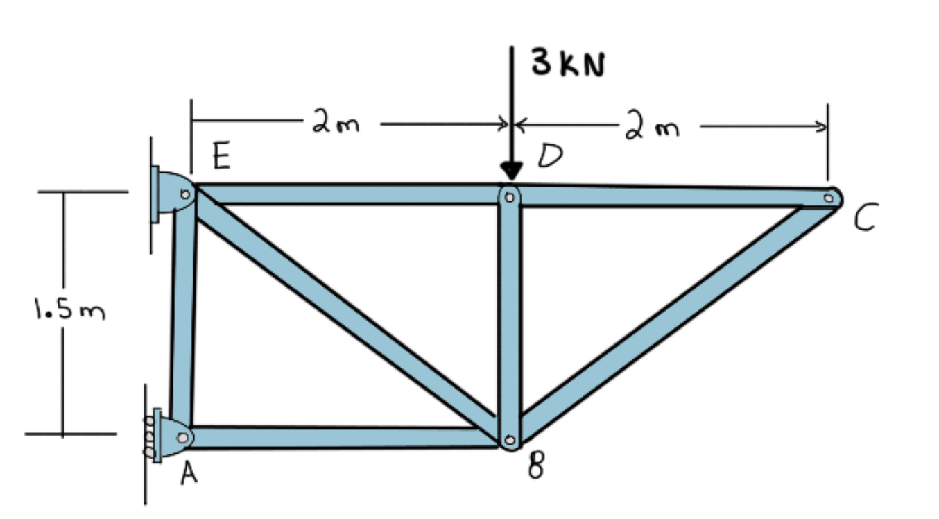
CB, DC, DE, AE

Mark Yourself Question
- Grab a piece of paper and try this problem yourself.
- When you're done, check the "I have answered this question" box below.
- View the solution and report whether you got it right or wrong.
Identify all Zero Force Members.